A GRE (Genereic Routing Encapsulation) is a tunneling protocol that allows data to be encapsulated and sent over a simulated point-to-point link. The beauty of it is that it will encapsulate many different types of traffic and De-encapsulate it on the other. This basically means any traffic sent to the tunnel interface will be stuffed it in a envelope and sent to the remote gateway, removed from the envelope, and forwarded normally. The network which the traffic is being routed across only sees GRE and not the individual IP header. A GRE tunnel can be used with or without IPSEC for encryption. This blog entry creates a tunnel WITHOUT IPSEC.
This is not only a one of the only ways to get Routing updates/traffic such as OSPF across a IPSEC VPN, but also is a wonderful troubleshooting option.I have seen this be a great troubleshooting tool when an MPLS might be blocking traffic.
Recently I have utilized a GRE tunnel to tunnel all multicast traffic across a MPLS network that does not support multicast. By tunneling all the Mulicast data, the MPLS only saw GRE packets and the multicast streams worked great.
In this post I will demonstrate how to create a GRE tunnel between two Fortigate firewalls. Traffic will then be encapsulated from the source and de-encapsulated and forwarded normally on the remote end point. Most of the GRE configuration within the Fortigate is CLI only and not something that can be configured in the GUI.
Steps needed
- Create System GRE tunnel, Assign local and remote gateways (WAN IPs)
- Modify system interface GRE settings and assign local/remote tunnel IPs (Tunnel IPs)
- Create Firewall policies to allow traffic
- Create routes to remote side of the tunnel , and select GRE tunnel as destination interface
- Test
The process is relatively straight forward and simple. First we need to create our GRE tunnel. The two sites we will be creating the tunnel on are Site-A, and Site-B.
Here is an overview of the network

Site A
CLI commandsconfig system gre-tunnel
edit “GRE-to-SITEB”
set interface “WAN1”
set remote-gw 2.2.2.1 — Remote firewall WAN IP
set local-gw 1.1.1.1 — Local FW WAN1 IP
next
end
config system interface
edit “GRE-to-SiteB”
set vdom “root”
set ip 192.168.254.1 255.255.255.255 — Local Tunnel IP
set allowaccess ping
set type tunnel
set remote-ip 192.168.254.2 — Remote Tunnel Endpoint IP
set snmp-index 65
set interface “WAN1”
next
end
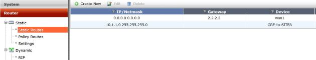
Route Creation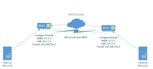
Now we can create the static route pointing my remote traffic (10.2.2.0/24) through the GRE-to-SiteB GRE tunnel.

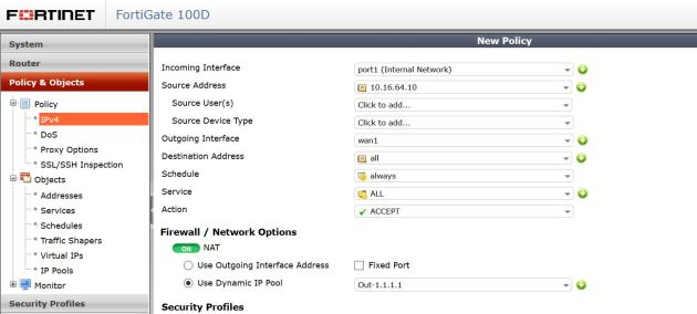
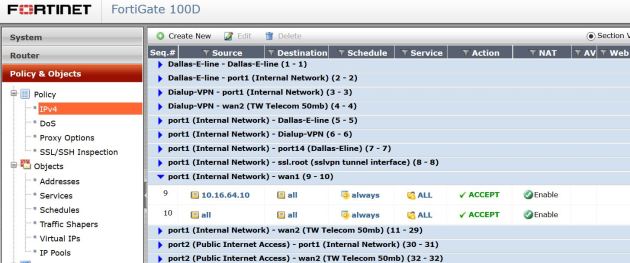
Firewall Policy creation
Next we need to create the Firewall policies allowing traffic from the GRE-Tunnel and to the GRE-Tunnel from the LAN interface or whichever interface your traffic originates on.

SITE B
GRE Tunnel creation
config system gre-tunnel
edit “GRE-to-SITEA”
set interface “wan1”
set remote-gw 2.2.2.1
set local-gw 1.1.1.1
next
end
config system interface
edit “GRE-to-SITEA”
set vdom “root”
set ip 192.168.254.2 255.255.255.255
set allowaccess ping
set type tunnel
set remote-ip 192.168.254.1
set snmp-index 8
set interface “wan1”
next
end
Route Creation
Now we can create the static route pointing my remote traffic (10.1.1.0/24) through the GRE-to-SiteA GRE tunnel.
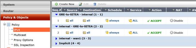
Firewall Policy creation
Next we need to create the Firewall policies allowing traffic from the GRE-Tunnel and to the GRE-Tunnel from the LAN interface or whichever interface your traffic originates on.
That should be it.
Now lets see if we can ping across our tunnel. As shown below pings work great! Pinging both the tunnel interface and across the tunnel are great ways to check if this tunnel is actually working. Odds are if you have enabled ping on the tunnel interface, and cannot ping it from the other side then the tunnel is not working. Also, check the Firewall policy count to make sure it is increasing with traffic – if so everything is working .


Thanks!