Tag Archives: Fortigate

Fortinet LDAP/RADIUS Source address with SD-WAN setup

I found this a neat tidbit of knowledge that I thought I should share.

Created a Fortinet SDWAN setup with many sites – works awesome. Fortinet’s SDWAN is simple, but very effective with some really cool features to help with SLAs.

During this setup, I have Radius, and LDAP servers located across one of the members of the SDWAN (An IPSEC tunnel). As before with tunnels, you would modify the source address in CLI for the destination server. This would make sure requests originate from the interface you are expecting, and will go through the tunnel.

After switching the tunnel to be a member of a SDWAN interface the LDAP/RADIUS requests stopped working. I found another command was needed. This command is needed not only for Radius, and LDAP but also for FAZ, Fortiguard, and dns.

In CLI of both Radius and LDAP servers you will see these options:

The trick here is to set the “interface-select-method” to sdwan. This resolved my issue and allowed things to start working. The reason it does this is that Self-originating traffic, such as Syslog, FortiAnalyzer logging, FortiGuard services, remote authentication, and others, relies on routing table lookups to determine the egress interface that is used to initiate the connection. Policy routes generated by SD-WAN rules do not apply to this traffic.

Setting up Static Addresses for Fortigate SSL VPN clients

I needed to have a specific SSL VPN client to always have the same IP address. This is not overly simple as it seems it should be. I have read there are very neat ways to do it through FortiAuth, or Radius options – but Here I am just doing all Fortigate configuration.

I am using a local account on the firewall in this example, but it would work with an AD users without issues – you would just have to map the user directly and not use groups.

SO, in this example I have a Scan gun that needs to have a specific IP every time it connects. So an overview of the steps are:

  • Setup SSL VPN (Should be already done if you are trying this).
  • Have LDAP or Radius integration already setup if you are specifically using that.
  • Setup Address object that you need the device to get – For this example 10.200.253.241.
  • Create a user object either local, or LDAP/Radius. – In this example Bargun01.
  • Create a specific portal if needed just for this user.
  • Create group/portal matching in SSL Settings.
  • Create firewall policy allowing that client in.

Ok, first lets create our address object .

Next lets create our user object – We need to do a specific user object, because we only want one device to be logged in and match this policy.

Then lets create the portal specific for this device – which only needs access to one server. In this portal we will match the it to the individual IP object we created, and set the remote access server it needs. Notice that the source IP Pool is the specific IP we set – this is where all the real magic is.

Next lets match up our user to the portal.

One more thing to do – and that’s to setup our firewall policy! Notice that the user matches what we put in the portal. Very specific. That’s it.

Enabling SNMPv3 on FortiOS 6.4.5

SNMPv3 should always be enabled if possible over v2.

First enable the SNMP agent and set the location/device name. Make sure to press apply down at the bottom of the page.

Next lets create the V3 user. You can do this by just clicking “Create New” Under the V3 options.

When you create the user you have options of Authentication algorithms, encryption, the IP of the monitoring host, and what they can monitor. Also, you can drop into CLI and change the source IP for traps.

Last part is now to enable SNMP on the interface you want to connect the monitor to. You only need to have SNMP enabled on the interface the monitor is connecting to, so just do a local LAN interface.

Make sure to click SNMP under the admin access of the interface, and click OK. Thanks it!

Fortiauthenticator – SMS only remote sync rule

I had an issue, well more of a specific formatting issue with Fortiauthenticator that I thought I would share. I have a client who is only use SMS with forticlient via fortiauth. The idea is that the user connects and authenticates to the SSL VPN, and then hits Fortiauth for token code that was sent to the client VIA SMS.

When using SMS with tokens, you have to have the users mobile number entered so it can send to them. Hard coding the users mobile number worked great, but for some reason I could not get the remote sync rule to pull in the mobile phone number. Below are the steps I used to fix this.

First in the remote sync rule under “LDAP User Mapping Attributes” modify the mobile data field with “mobile” all lower case.

Then make sure that in Active Directory the mobile number is entered under the users profile. the Auth says it wants the mobile phone number in a very specific format – +[international_number] – this threw me for a while. In the end the number in AD wasn’t the problem it was the mapping attribute. Below is how to inset the number into AD. Notice the number has +[country code]number. Thats it, after putting that in the remote sync rule worked fine.

Getting Fortiswitch interface statistics

I am more impressed with Fortiswitches every time I work with them. The ability to implement light NAC features, INTRAvlan firewall policies and overall management really gives these switches a feature set to checkout when deciding on new switches.

Below are the steps to quickly get the interface stats such as errors/packets, etc. The commands are ran on the Fortigate, which in this case is controlling the Fortiswitch.

Drop into CLI on the FGT and check what switches are connected by running the command

get switch-controller managed-switch

This command will bring back the names of the manged switches. Locate the switch you want to check the port stats on. For example, we will use the name “FS1D24T419001174”

the command to get the stats are:

diag switch-controller switch-info port-stats FS1D24T419001174 port1

The output is in the image below:

using the top level command diag switch-controller switch-info you can also get LLDP, Power, and lots more info of the managed switch.

Updating or Rekeying Fortigate certificates

Certificates for VPN, SSL Offloading (if using Load balancing), or a signed device cert expire, we all know this. Up until last week I had never updated a signed certificate, I had just created a new CSR, and rekeyed the cert. Updating the certificate the Fortigate is using is very easy, but I had problems with the syntax so I am documenting it here.

The Fortinet KB article to do it is located here:

https://kb.fortinet.com/kb/documentLink.do?externalID=FD35074

I had an issue following the doc so I though I would clear the water and see if I could help someone down the road. Lets say I have sslvpn.travelingpacket.com that will expire in 2 days – I log into my CA (godaddy in my case) and renew the cert. They send the new cert to me, but what do I do with it…

Open the cert with a text editor – maybe notepad – and copy the cert. you should see —BEGIN CERTIFICATE. Copy everything. Then log into the fortigate VIA cli – Putty or some kind of SSL client is way better for doing this then the web client. Then lets modify the certificate

config vpn certificate local

edit sslvpn (or your cert name)

set certificate “—–BEGIN CERTIFICATE—– mPjDQDYkYHKcTrGa6aH7e1w1uM7kdaBAjyAgM7xcmuTrsCeLYfd+BwIDAQABo4IDTDCCA0gwPQYJKwYBBAGCNxUHBDAwLgYmKwYBBAGCNxUIorRWhO7dYIKtkziB9KY0
>—–END CERTIFICATE—–“

and Press enter – The issues I had was with the quotes. I tried to first do double quotes, and past the cert in the middle – that does not work. Just simply type in the command set certificate and then a double quote and past the cert whole. After its pastes do the ending quote and press enter.

IMPORTANT: That’s it for modifying the cert – but to enact it we have to remove it from whatever we are using it for, and then add it back. That refreshes the cert. So if your using it for SSL-VPN , go to VPN – SSL-VPN settings – and set the server cert to a different one, press apply, and change it back.

Clearing sessions in FortiOS

Fortigate firewalls are stateful by design, this means that when a client behind the firewall talks to lets say Google a session is created – If all security policies are met.  Google’s return traffic can automatically come back into the client, following the same path (Session) without having to explicitly have an access rule that allows that traffic.  This is also very beneficial in security because the firewall keeps track of that session, makes sure all traffic is flowing on the session as it should, and will close the session if needed. When the session is closed Google cannot talk to our internal host anymore without following very specific rules that would allow communication from them.

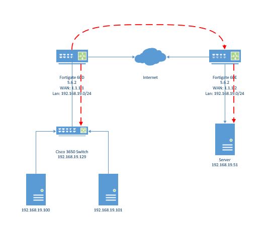
With remote APs, Video streams, any many more (Specifically UDP streams) I see problems a lot with sessions getting created on the WAN (Default route) for RFC-1918 private subnets. When this happens internal clients – Maybe APs – cannot talk back to the controller or the UDP video encoder cannot find the decoder any more, but other clients can communicate with those devices just fine.

The reason this happens is that most of the time the IPSEC VPN tunnels or MPLS/E-LAN interfaces have static route assigned to them for getting to the other side subnets. If the physical interface or VPN interface drops then what routes exist in the routing table? Thats right – just the default which in turn sends all traffic even for private subnets out to the internet.  Lets take a UDP video Stream  between two locations for example -UDP never needs an acknowledgement of the traffic, so it keeps blasting traffic to the session – when the session gets created to the internet

When those interfaces or tunnels come back online all should work, and will unless traffic never stops flowing, which is where our problem lies.  When traffic tries to flow when all interface routes are down, then the only route left is the default – so the session gets created on the WAN interface.

To clear these sessions and fix the issues there are a few options.

1 – clear all sessions of the firewall

2 – create session filter and only clear the sessions you need to .

There are many other reasons to clear sessions than the reason I mentioned above.  So lets get to commands!

First you can show sessions on the firewall by using:

options1.JPG

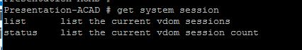
Status will show you how many active sessions you have on the firewall and List will print out the individual sessions.

When you select list you get the following information

list1

So for this example lets check out the session created from my internal host 10.3.0.1 going to 104.197.225.108 (www.mirazon.com).

list 2

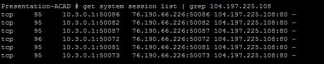
So we see that just by going to http://www.mirazon.com it opened 6 session, these are all going to the same destination IP/Port but coming from different source ports. Option 1 was we could clear all sessions from the firewall – the command to do that is:

diag system session clear

In this example, lets say I want to clear only sessions going to IP 104.197.225.108. We need to create a session filter and then clear only those. Here are the following options on creating filters

filter-1

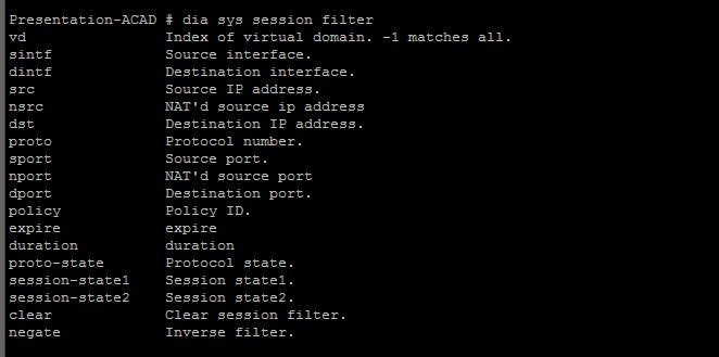
Lots of options – one of the coolest in my opinion is matching on Protocol! But in this case lets match by destination IP.

filter-clear

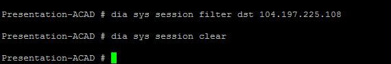
Thats it! now we have cleared all sessions going to that IP.

NOTES

A few things to note – The firewall will clear out a session  if it does not see a keepalive. It will do that every 3600 seconds by default – this means if a voice call is going on through the firewall then it might close the session after 3600 seconds – this can be a big problem. The “dia system session list” is a great way to find a session and see when it will expire. Great way to troubleshoot – you can also use the GREP keyword to help find exactly what you want.
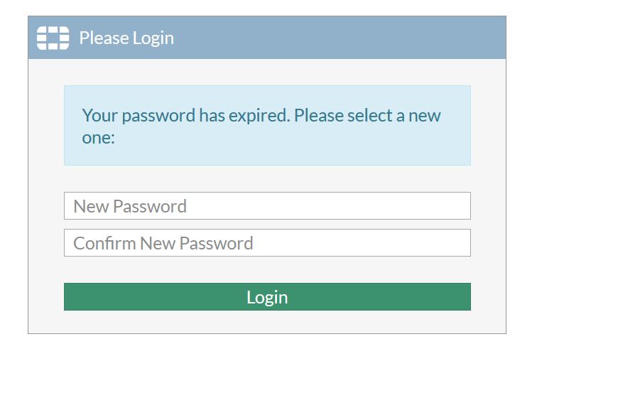


Fortigate VXLAN Encapsulation over IPSEC

VXLAN is a Layer2 overlay scheme over a Layer 3 network. VXLAN uses MAC Address-in-User Datagram Protocol (MAC-in-UDP) encapsulation to provide a means to extend Layer 2 segments across a layer3 segment. This basically means the layer2 packet gets a VXLAN header applied, then that frame gets encapsulated into a UDP IP packet and sent over to the layer3 network.

In later FortiOS 5.4 firmwares VXLAN (Virtual Extensible LAN) encapsulation was added. This is a great technology that can help connect to sites at layer2 over layer3. Something to take note of – as of FortiOS 5.6.2 – lots of improvements and enhancements to VXLAN encapsulation have been made. For example, vlan trunking works well now. Mutlicast also will traverse the VXLAN!

So far I have set this up for two different clients. Both were situations where we had to have layer 2 stretched for a certain purpose. in the last case it was to two different data centers. Below is the scenario and config of the Fortigates as well as show ARP/MAC from the Cisco switch. Fortinet has some great documentation as well on this feature (Links below).

http://kb.fortinet.com/kb/documentLink.do?externalID=FD38614

http://kb.fortinet.com/kb/documentLink.do?popup=true&externalID=FD40170&languageId=

Below shows our simple layout. The red line indicates the VXLAN encapsulation path. Encapsulation only happens at Fortigate firewalls.

layout

Here is a check lists of things that are needed:

  • Create VXLAN VPN
    • Local encap-local-gw4 is the public address on the local FW
    • encap-remote-gw4 is the peer address of the other side
    • remote-gw is the peer address of the other side
  • Then create a new Switch interface
    • Add both the local network, and VXLAN-VPN interface to this switch
  • Create firewall policies allow traffic

Thoughts and observations:

  • Lowering the MTU of the VXLAN/internal interface might be a good idea. The VXLAN encapsulation adds around 50-bytes. Most Cisco documentation will mention increasing the MTU, but since we are going over the net with this, increasing MTU means lots of fragmentation.
  • No IP address on the Switch interface is needed. Actually I have seen small issues when putting an IP address on the interface.
  • In CLI use the commands below to help get broadcasts (be careful) and ARP to go across.
    • config sys int
      • edit VXLAN
        • set l2forward enable
        • set broadcast-foward enable
        • end
      • end
  • In 5.6.2 VLANs tags will pass through the tunnel

CONFIG

SIDE 1 (60D)

config vpn ipsec phase1-interface
edit “VXLAN”
set interface “wan2”
set peertype any
set proposal aes256-sha1
set encapsulation vxlan
set encapsulation-address ipv4
set encap-local-gw4 1.1.1.1
set encap-remote-gw4 1.1.1.2
set remote-gw 1.1.1.2
set psksecret password
next
end
config vpn ipsec phase2-interface
edit “VXLAN_ph2”
set phase1name “VXLAN”
set proposal aes256-sha1
next
end

config system switch-interface
edit “VXLAN-SWITCH”
set vdom “root”
set member “internal1” “internal2” “VXLAN”
next
end

Lets look at the Switch in the gui

60d-switch

Then lets check out the Firewall Policies

firewall policies

SIDE 2 (60E)

config vpn ipsec phase1-interface
edit “VXLAN”
set interface “wan1”
set peertype any
set proposal aes256-sha1
set encapsulation vxlan
set encapsulation-address ipv4
set encap-local-gw4 1.1.1.2
set encap-remote-gw4 1.1.1.1
set remote-gw 1.1.1.1
set psksecret password
next
end
config vpn ipsec phase2-interface
edit “VXLAN_ph2”
set phase1name “VXLAN”
set proposal aes256-sha1
next
end

Lets look at the Switch in the Gui

60-e interface

Next lets check out the Firewall Policies

fw-60e


Testing

First make sure the VPN is up and working. Then a simple ping test between two devices on the same subnet will be enough to make sure things are working. TCP is always the best way to test . You can also check and make sure that the ARP/MAC address tables on each side show something on the remote side. For example the below shows the ARP/MAC of the Cisco 3650 switch at the Datacenter side (60D).

Datacenter-Stack#show arp

Protocol  Address          Age (min)  Hardware Addr   Type   Interface

Internet  192.168.19.21           0   000c.291c.b2a5  ARPA   Vlan1


Internet  192.168.19.51           0   000c.2918.b8be  ARPA   Vlan1  – 19.51 lives behind the 60E

Datacenter-Stack#show mac address-table
Mac Address Table
——————————————-

Vlan Mac Address Type Ports
—- ———– ——– —–
1 000c.2918.b8be DYNAMIC Gi1/0/1  — Fortinet 60D is connected to gig 1/0/1


Conclusion

Thats it! VXLAN is an open source protocol that is a great datacenter technology. Fortinet makes it very easy to get this up and going within a few minutes. EB

FGT traffic shaping in 5.4 – Per Policy/shared options

The best docs are always at docs.fortinet.com

Fortigate traffic shaping is awesome, lots of options and it all works really well. Going from 5.2 to 5.4/5.6 is quite different due to the creation of policies changing from within the firewall policy, to their own section. Either way, they all work great.

I did notice at least in 5.4 that the option to change how a policy is used do not seem to be in the GUI. Previously there were two options – “Per Policy”, and “all policies using this shaper”. Selecting “all policies using this shaper” would have all policies using that shaper object to share the guaranteed or Max bandwidth settings between all policies using that shaper. Selecting “Per Policy” allows you to dedicate those same settings to each policy referencing the shaper object.

Which gets to my point, in 5.2 you had the options below. Notice the options about how to apply the shaper.

5-2

In 5.4.5 at least notice that they are gone. Of course, if you upgraded from 5.2 the options are there.

5-4

So as with everything that does not show up in the GUI – you know it is in CLI. So I dropped down to CLI to check if the settings are still there. By editing the shaper, and using the “get” command I could see all settings and their values the policy had to offer. As I thought the option “Per-Policy” is there with the default settings of disabled. So by default, all Shaper policies have  settings shared between different traffic policies referencing that shaper.

edit-shaper

So in this case, I want to give the same percentage of bandwidth to each of the traffic shaper policies referencing my shaper object. So I will modify that option.

set-options

Now, in the GUI lets check that policy again –

after-changes

Awesome, now we have the actual options to change.