Category Archives: Cisco
Cisco ASA 8.2 and Below – Static Nat
The other day I had to configure a Static nat entry on a 8.2 ASA. It had been a while since I had done this since almost everything I work with is 8.3 and above. I thought I would make an entry for myself and maybe to help someone along the way.
Example – I have public IP 1.1.1.10 and I need to forward in port 443 to my internal server of 192.168.1.10. I have an access-list Outside-IN applied to my outside interface. Note if the 1.1.1.10 is my outside interface IP (lets say I have only one public IP) then we would use the interface key word
ASA config –
config t
static (inside,outside) tcp 1.1.1.10 443 192.168.1.10 443
access-list Outside-IN permit tcp any host 1.1.1.10 eq 443
or
static (inside,outside) tcp interface 443 192.168.1.10 443
access-list Outside-IN permit tcp any host 1.1.1.10 eq 443
That’s it!
Compared to 8.3 and above –
object network 192.168.1.10
host 192.168.1.10
nat (inside,outside) static interface service tcp 443 443
access-list Outside-IN permit tcp any host 192.168.1.10 eq 443 — Notice the internal IP.
Cisco Switch – Set interface back to defaults with one command
As easy as it is, I always forget this command.
The following command will set an interface to defaults. Lets say I have about 10 commands on the interface specifying Voice, Access, Trunk, Spanning tree – etc, and I want to quickly throw that port back to default. I can issue this command
config t
default interface gig 1/0/1
And its back to default, no configuration!
This command was introduced in IOS 11.1, so it should be in about every switch out there now.
Cisco IP-SLA to track interface state
Sometimes it is necessary to track an interface state to bring down a certain route.
In my case I have a Multihomed scenario, and two routers. In this case the upstream routers do not know about each other, the downstream routers make the routing decisions for the network.
I have a static route configured pointed to the ISP, I am redistributing that static route to my clients through OSPF. If the state goes down on the interface then the router will take it out of its routing table. You can do this by pining an IP address, UDP Jitter, State, etc.. many ways.
Commands:
config t
track 100 interface GigabitEthernet0/2 line-protocol
ip route 0.0.0.0 0.0.0.0 1.1.1.1 track 100
exit
You can use commands like:
show track
show track int
show track bri
Cisco Preshared Key recovery options
The other day I had to copy the config of an ASA and a PIX to other devices. They both had VPNS to different sites and I had to have those keys as no one documented them.
A few different ways to get those keys are:
ASA
Option 1: Login using ASDM and make a full backup including preshared keys
Option 2: Run the cli command :
more system:running-config
Option 3: Copy running config to a TFTP/FTP server
PIX
The above options exist for the PIX as well. I have read that the more command will work , but it did not for me. Then I found this option to get the Keys on the pix:
Enable http server, create a username and go to https://pix-ip/config the key is then shown in clear text.
Commands to do that:
config t
http server enable
http 0.0.0.0 0.0.0.0 inside
username admin password password
The go to the web interface.
Time based Policy-map for traffic policing
Recently I was tasked to resolve a problem where a video stream on Saturday and Sunday would get very choppy. This video stream is for a church and as you would expect needs to be perfect. There are multiple remote sites each connected to an MPLS back to the core site which is where the video stream originates. Each site has a 100Mb MPLS link back to the core site.
We wanted to make sure that on Saturday and Sunday that normal traffic (web, file shares) would be capped at around half the useable bandwidth, and the other half was for the stream. This is much more bandwidth than what the stream needs, but we want to make sure its plenty.
So, what we did was implement time based ACLs for both the traffic we want to prioritize, and another ACL for all default traffic that we want to police. We used a ‘any-any’ ACL instead of the class-default because we have to make it time based.
Some of the things to note – the Burst rate really mattered here. I followed the formula from Cisco RATE-SPEED/8 * 1.5. Using this formula solved my issues and things flowed exactly the way I wanted them to.
To test I changed the time on the router to look like Saturday, and then used Iperf to push traffic.
The system clock on the router has to be correct, else everything can be very screwed up. You might be saying why did you use a policer instead of a shaper? good question. I would have used a shaper if my 3750’s supported it. A shaper would have been a better solution here.
Steps
– Create Time-range
– Create ACLs using time range
– create class maps
– create policy maps
– apply policy-map to interface
First to create the time-range to match the times we wanted we used the following commands:
config t
time-range Weekend-Service
periodic Saturday 13:00 to Sunday 15:00
exit
Next I created the ACL to match the priority traffic and default traffic
ip access-list ext Priority-traffic
10 permit ip host 10.0.0.1 any time-range Weekend-Service
exit
ip access-list ext Default-Traffic
10 permit ip any any time-range Weekend-Service
exit
Then I created the class and policy map, and attached it to the interface.
Class-map match any Priority-Traffic
match access-group Priority-Traffic
exit
class-map match-any Default-Traffic
match access-group Default-Traffic
exit
policy-map Stream
class Priority-Traffic
set ip dscp ef
exit
class Default-Traffic
police 50000000 937500
set ip dscp default
exit
int gig 1/0
policy-map input stream
exit
There are many commands to test the status, one command is “show policy-map interface”
HP vs Cisco Vlan trunking
Whenever I talk to networking people about integrating or replacing Cisco switches with HP they always talk about how difficult it was to get them to pass vlan info. This is because the terminology is totally different between the two.
In the Cisco world a “Trunk” port will pass all vlan tags by default. What does this mean? It means that the port can accept/pass IP packets with different Vlan tags. Basically the trunk port is a member of every vlan, and therefore will pass traffic from every vlan its a member of. In HP the word Trunk means link aggregation example is LACP. Basically taking 2 or more links and combining them. HP uses the phrase “tagged”.
So what is a VLAN tag?
The “Vlan ID” is a 12-bit value in the IP header of the Ethernet frame that specifies which vlan that frame belongs, and thus virtually separates traffic.
So to configure a port as a trunk in Cisco the command is “switchport mode trunk”. This will allow the port to access every vlan , and understand/pass the frames with any tag.
In HP world you would “tag” multiple vlans on a single port. The “tag” command basically means that the port can pass/understand frames in those “tagged” vlans on that port. So lets say we have 2 vlans, and we want a switch to pass frames on both vlans to another port, then we would configure the port as tagged in both Vlans. Commands would be:
int 24
tagged vlan 120,140
Now that port will accept tags from both vlans and pass them along.
Access ports or Untagged
An access port in Cisco is a port who’s traffic will be tagged by the switch for the vlan the port is set to access. For example if the command on the port is “Switchport access vlan 120” then all untagged (default) traffic will be tagged for vlan 120 by the switch. This is done because the host itself is not tagging frames, but sending everything untagged.
In HP this access port would be “untagged”. This means that the traffic leaving the port will come in untagged, but will be tagged with vlan X by the switch. So the command – “untagged vlan 120” means all traffic will be in vlan 120.
Commands:
Trunk ports
Trunk (cisco)
int gig 1/0/24
switchport mode trunk
exit
Trunk (HP)
int 24
tagged 120,140
exit
Access ports (this port is in this vlan)
Access (cisco)
int gig 1/0/24
switchport mode access
switchport access vlan 120
Access (HP)
int 24
untagged 120
Cisco ACL Logging: log-input
Using ACL logging can be a very useful tool not only to get info about whats going on, but also for troubleshooting. One way to get much more robust logging is to use the log-input at the end of the ACE.
The log-input command shows the normal things such as source ip/port and destination ip/port but will also so the ingress interface and mac address of the source. Very cool! The following is and example of the output:
*May 1 22:33:38.799: %SEC-6-IPACCESSLOGP: list ACL-IPv4-E0/0-IN permitted
tcp 192.168.1.3(1025) (Ethernet0/0 000e.9b5a.9839) -> 192.168.2.1(22), 1 packet
*May 1 22:39:15.075: %SEC-6-IPACCESSLOGP: list ACL-IPv4-E0/0-IN permitted
tcp 192.168.1.3(1025) (Ethernet0/0 000e.9b5a.9839) -> 192.168.2.1(22), 9 packets
Cisco ASA IPSEC site to site VPN IOS 8.3+
There are multiple parts to the IPSEC SIte-to-Site VPN config.
– Create access list to specify what will be encrypted
– Create access list to specify what should go over the VPN, and not be natted
– Create Phase 1 (IKE) settings and apply it to the selected interface.
– Create our transformation set (what encryption settings we will use for phase 2).
– Create Phase 2 (ESP) settings otherwise known as a Crypto map.
– Apply Crypto map settings specifying interface.
– Create the tunnel object for peer.
Config:
ASA 1 Core
Create Objects
First create the objects representing what will be found on each side of the VPN.
config t
object network Local-Subnet
subnet 10.100.1.0 255.255.255.0
object network Remote-Subnet
subnet 10.100.2.0 255.255.255.0
Encryption Access-list
Next I will create the Access list to tell the firewall what to Encrypt
access-list VPN-to-Remote extended permit ip object Local-Subnet Remote-Subnet
Now we need to make sure traffic is not being forwarded out of our WAN interface, and that the firewall knows to send it over the VPN. We do this with a “No-Nat” statement. This is different than what it once was in 8.2 and below. We will specify this with a different kind of nat statement.
No NAT
nat (inside,outside) source static Local-Subnet Local-Subnet destination static Remote-Subnet Remote-Subnet
IKE Settings
Now its time for the VPN settings!
First lets create our IKE settings and enable it on the outside interface.
crypto ikev1 enable outside
crypto ikev1 policy 1
authentication pre-share
encryption 3des
hash sha
group 2
lifetime 86400
Create the IPSEC transformation
crypto ipsec ikev1 transform-set transfrom esp-3des esp-sha-hmac
Crypto MAP (Phase 2)
Now lets create our Crypto map and put it all together.
crypto map VPN 10 match address VPN-to-Remote
crypto map VPN 10 set pfs
crypto map VPN 10 set peer 1.1.1.2
crypto map VPN 10 set ikev1 transform-set transfrom
crypto map VPN 10 set security-association lifetime seconds 28800
crypto map VPN 10 set security-association lifetime kilobytes 4608000
There are a few optional settings like the lifetime, by default its 28800. In this config I am just making it known that’s what its set on. Also you can set “reverse-route” which will add the route to the remote subnet into the routing table. This way you can push it out in a routing protocol.
We will also need to apply the Crypto map to the interface.
crypto map VPN interface outside
Tunnel Group/PSK
Our last step is to create the tunnel group with our Peer IP/DNS name and set the PSK.
tunnel-group 1.1.1.2 type ipsec-l2l
tunnel-group 1.1.1.2 ipsec-attributes
ikev1 pre-shared-key presharedkey
Below is the config for the Remote side
config t
object network Local-Subnet
subnet 10.100.2.0 255.255.255.0
object network Core-Subnet
subnet 10.100.1.0 255.255.255.0
access-list VPN-to-Remote extended permit ip object Local-Subnet Core-Subnet
nat (inside,outside) source static Local-Subnet Local-Subnet destination static Core-Subnet Core-Subnet
crypto ipsec ikev1 transform-set transfrom esp-3des esp-sha-hmac
crypto ikev1 enable outside
crypto ikev1 policy 1
authentication pre-share
encryption 3des
hash sha
group 2
lifetime 86400
crypto map VPN 10 match address VPN-to-Core
crypto map VPN 10 set pfs
crypto map VPN 10 set peer 1.1.1.1
crypto map VPN 10 set ikev1 transform-set transfrom
crypto map VPN 10 set security-association lifetime seconds 28800
crypto map VPN 10 set security-association lifetime kilobytes 4608000
crypto map VPN interface outside
tunnel-group 1.1.1.1type ipsec-l2l
tunnel-group 1.1.1.1 ipsec-attributes
ikev1 pre-shared-key presharedkey
Checking user license limit in Cisco ASA 5505
I work with many Cisco ASAs in the field that have been purchased from ebay then put into production. They work great, but sometimes people cannot connect, or in one instance the device kept rebooting.
This was because of the license limitation of the device.
The ASA has two main licensing modes, base and security plus.
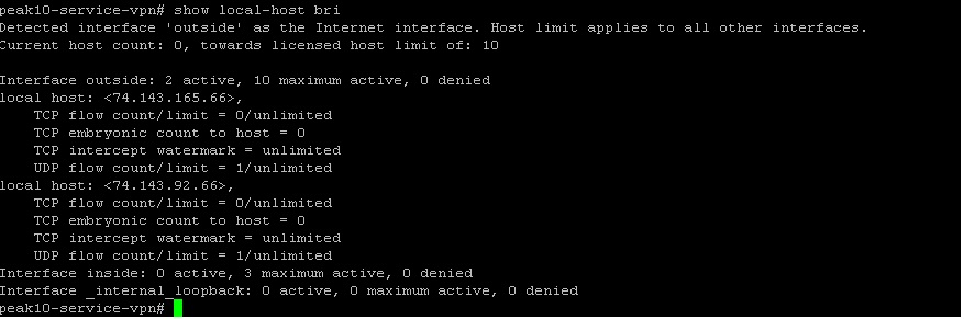
Base allows a user limit of 10, so what is a user?
A user is any host that communicates with the “outside” vlan/interface. If you want to check how many users are in use run the command “show local-host brief”
So in this case only 2 users are counted. This number will increase and decrease as users timeout.
To extend the user limit you can upgrade to optional 50, or unlimited license level within base, or just get the security plus with unlimited.
Cisco of course has a ton of licensing options, here is the link for Cisco 5500 series http://www.cisco.com/c/en/us/td/docs/security/asa/asa82/license/license82.html#wp204305
Cisco ASA Packet capture
Within the Cisco ASA you can capture packets within the CLI or ASDM. Here I will be demonstrating the CLI Method. You can find the ASDM method under – wizards – packet capture
The other day I had a botnet on a internal client that would start communicating at strange hours, so it was hard to get info without a syslog server. I created a ACL within the ASA with the destination IP and then started a capture to get all traffic going to that destination. Below are the steps
1. Create ACL to grab traffic you want to capture
access-list Botnet ext per ip any host x.x.x.x
2. Start the capture to grab the ACL traffic
capture Botnet-traffic interface inside access-list Botnet
3. Check the traffic capture:
show capture Botnet-traffic
All commands show below:
config t
access-list Botnet ext per ip any host x.x.x.x
capture Botnet-traffic interface inside access-list Botnet
show capture Botnet-traffic