Tag Archives: Fortigate

Fortigate 5.4 – Named policies

Fortigate has done a great job with the 5.4 firmware. Its a big change from 5.2 but once you get going with it, you will find things are structured very well. For example the “Monitor” category is a great way to get everything you need, instead of going through each individual category.

One feature of 5.4 that really “Grinds my gears” is the named policy feature. The feature itself is awesome, great way to put in a name on a policy such as “Students to internet”.. etc.  But, they make it mandatory to put in a name by default. What’s so aggregating about this is that if you upgrade to 5.4 from 5.2 all of your policies are unnamed, so when you modify one of those existing policies you HAVE to put in a name. The following will show how to turn that feature off, so it is not mandatory you put in a name. You still can, just don’t have to.

Below you will see what happens when you try to create that policy , and the the feature has not been disabled. You get the “This field is required.” error. It will not let you create or modify the policy until that is filled in.

rule-creation-error

To disable this feature, go to system-Feature select- then check “Allow unnamed policies”. Once you press Apply this will let you bypass the mandatory name feature.

services

Fortigate: GRE tunnel creation

A GRE (Genereic Routing Encapsulation) is a tunneling protocol that allows data to be encapsulated and sent over a simulated point-to-point link. The beauty of it is that it will encapsulate many different types of traffic and De-encapsulate it on the other. This basically means any traffic sent to the tunnel interface will be stuffed it in a envelope and sent to the remote gateway, removed from the envelope,  and forwarded normally. The network which the traffic is being routed across  only sees GRE and not the individual IP header. A GRE tunnel can be used with or without IPSEC for encryption. This blog entry creates a tunnel WITHOUT IPSEC.

This is not only a one of the only ways to get Routing updates/traffic such as OSPF across a IPSEC VPN, but also is a wonderful troubleshooting option.I have seen this be a great troubleshooting tool when an MPLS might be blocking traffic.

Recently I have utilized a GRE tunnel  to tunnel all multicast traffic across a MPLS network that does not support multicast. By tunneling all the Mulicast data, the MPLS only saw GRE packets and the multicast streams worked great.

In this post I will demonstrate how to create a GRE tunnel between two Fortigate firewalls. Traffic will then be encapsulated from the source and de-encapsulated and forwarded normally on the remote end point. Most of the GRE configuration within the Fortigate is CLI only and not something that can be configured in the GUI.

Steps needed

  • Create System GRE tunnel, Assign local and remote gateways (WAN IPs)
  • Modify system interface GRE settings and assign local/remote tunnel IPs (Tunnel IPs)
  • Create Firewall policies to allow traffic
  • Create routes to remote side of the tunnel , and select GRE tunnel as destination interface
  • Test

The process is relatively straight forward and simple. First we need to create our GRE tunnel. The two sites we will be creating the tunnel on are Site-A, and Site-B.

Here is an overview of the network

GRE-overview

Site A

CLI commandsconfig system gre-tunnel
edit “GRE-to-SITEB”
set interface “WAN1”
set remote-gw 2.2.2.1    — Remote firewall WAN IP
set local-gw 1.1.1.1          — Local FW WAN1 IP
next
end

config system interface
edit “GRE-to-SiteB”
set vdom “root”
set ip 192.168.254.1 255.255.255.255    — Local Tunnel IP
set allowaccess ping
set type tunnel
set remote-ip 192.168.254.2                  — Remote Tunnel Endpoint IP
set snmp-index 65
set interface “WAN1”
next
end

Route CreationGRE-overview.JPG

Now we can create the static route pointing my remote traffic (10.2.2.0/24) through the GRE-to-SiteB GRE tunnel.

Route-SiteA

Firewall Policy creation

Next we need to create the Firewall policies allowing traffic from the GRE-Tunnel and to the GRE-Tunnel from the LAN interface or whichever interface your traffic originates on.

Policy-SiteA


SITE B

GRE Tunnel creation

config system gre-tunnel
edit “GRE-to-SITEA”
set interface “wan1”
set remote-gw 2.2.2.1
set local-gw 1.1.1.1
next
end

config system interface
edit “GRE-to-SITEA”
set vdom “root”
set ip 192.168.254.2 255.255.255.255
set allowaccess ping
set type tunnel
set remote-ip 192.168.254.1
set snmp-index 8
set interface “wan1”
next
end

Route Creation

Now we can create the static route pointing my remote traffic (10.1.1.0/24) through the GRE-to-SiteA GRE tunnel.

Route-SITEB

Firewall Policy creation

Next we need to create the Firewall policies allowing traffic from the GRE-Tunnel and to the GRE-Tunnel from the LAN interface or whichever interface your traffic originates on.

Policy-SiteB

That should be it.

Now lets see if we can ping across our tunnel. As shown below pings work great! Pinging both the tunnel interface and across the tunnel are great ways to check if this tunnel is actually working. Odds are if you have enabled ping on the tunnel interface, and cannot ping it from the other side then the tunnel is not working. Also, check the Firewall policy count to make sure it is increasing with traffic – if so everything is working .

site-a-pings

site-a-count


Thanks!

Fortigate – Changing outbound nat IP with IP Pools

Sometimes it is necessary to change IP address used to talk with the internet that the internal client is using. For instance it is always important to make sure your SMTP server is using the same outbound IP used for inbound traffic. I have seen this cause a good many mail servers to be blacklisted by ISPs. In the following entry we will change the IP the client is using for outbound nat.

This technique has many awesome benefits, you can nat into this IP (IP pool) only when going to a certain destination.. etc. For example, if you had to change your source IP when accessing a destination across a VPN tunnel. That example might be very important in a medical field where I have found you almost always have to nat your private traffic to a public address when accessing the VPN hosts.

The internal client address is 10.64.16.10, external IP is 1.1.1.1. In this example I only want this one internal client to be natted out of 1.1.1.1

So we have to create a Virtual IP pool . We create the Virtual IP pool by going to Policy and objects – objects – IP Pools

IP pool-create

We then can setup the pool. Notice the options

– Overload allows PAT, so many ip addresses, to one public.
– One-to-One allows one IP to that public IP
– We also have the option to nat into a Public Range of addresses

We also want this device to answer VIA Arp for 1.1.1.1

Now lets create our IPv4 Policy to allow our private IP address to be allowed to the internet (WAN1) and to be natted VIA this IP pool. I created the address object for my private host already.

policy-creation

So after creating our IPV4 policy, we have one thing left to do – make sure this is one of our first policies hit when 10.16.64.10 tries to access the internet. So lets make sure its at the top of our list, or at least above our default nat rule.

above

That’s it! if you now go to a site such as ipchicken.com or whatismyip.com you will see 1.1.1.1 if you are coming from 10.16.64.10.

Fortinet – Creating vlans for devices directly connected to device

The other day I had the need to plug a Ruckus Access point directly into the Fortigate firewall. The client only needed 1 AP, and connecting directly into one of the ports on the Fortigate was the best way – PoE was provided by an injector.

The question came up of how to create the Vlan interface when directly connecting the device to Fortigate.

In this example I will create the vlan on the Internal switch “lan”, and control the vlan from the Ruckus Zonedirector. This will create two separate logical interfaces. Internal, and Staff-Wireless, my newly created vlan.  These two interfaces will require IPV4 policies to allow communication. If you have a lot of VLANs it might be a great idea to utilize Zones in the FW to reduce the number of firewall policies needed.

Lets get started

Vlan creation of Fortigate

So, lets create the vlan for “Staff-Wifi” Vlan 200. You can just create

create-interface

Now lets put in the needed info.

Interface

The below shows the status of the interface:

show-int

Notice the VLAN ID – this is seen by right clicking the column settings and enabling that.

Thats it! The Ruckus AP will tag “Staff-Wireless” traffic as vlan 200. So, when the FGT sees the vlan tag of 200 on any ports in the lan switch, it will be treated as Staff-Wifi, thus getting all of its network and policies.

To make the AP work correctly, it needs to be plugged directly into the FGT or a switch behind the FGT that has the vlan created and that vlan would need to be tagged on both the AP and uplink to Fortigate.

Below shows the advanced options of my Ruckus  ZD. I am tagging the Staff-Wifi SSID as vlan 200.

Ruckus.JPG

Remember on the Ruckus side only vlan 200 is being tagged for Staff-wifi AP management traffic is untagged – so it would be on my “LAN” switch network.


Blocking geographic regions in Fortigate 5.4

The best docs are always at docs.fortinet.com

Sometimes I get asked by clients how to block know attacking countries like Russia, or China from accessing their websites. I often hear that only US connections would be accessing their services so why allow others who might not be on the up and up.

Of course most attackers might pivot from compromised computers in the US, and thus bypass this security feature, but either way its not a bad idea. The below gives a good example on how to create a firewall “country” group and then block those countries from accessing any services hosted through the firewall. This will be done in Forti-OS 5.4.0. Its really the exact same steps in 5.2.

Also, there are many ways to do this. Instead of blocking Geographic regions you could only allow the ones you want to give access to.

Before beginning it might be a great idea to check out the new Fortiview feature to see what countries access your services the most. Under Fortiview- you can now see the countries tab.

Monitor-Countries


Great, so in this example lets block the region of China – I know its not one of the top countries accessing my services.

First lets create the address object that we want to block. In this case I am setting the name of the address object as the country I am blocking. After creating the country object, I will create an address group call “Country blocks” add this to my firewall policy. That way in the future if I want to block Ireland, I can just add that object in the group and I am done.

Creating the address object for “China”. First go to “Policy & Objects” and create a new object.

create address

Next we will fill in the needed info, and change the address type to “Geography”.

China

Now lets great that group, and add the “China” object to it.

Country-Group

Awesome, now just one more step – creating the firewall policy to block this address group.

block-policy

Press OK, move this policy to the top of all WAN-LAN or your interfaces policies. This way it gets hit before anything else.

There are more ways than 1 to do this. when allowing traffic into your VIP or policy you could instead specify only the allowed countries.


Foritgate 5.4- Changing the interface theme

In 5.4 you now have the option to change the interface color. This is a great setting, because I am not a fan of the emerald green interface that’s default.

This is a great option, and easy to change.

To change the color just navigate to System – settings. At the bottom under view settings you will see the option to change the theme. There are currently 4 colors available. Green, red, blue, and my favorite Melongene. Good Job Fortinet!

Below are screenshots of how to do this.

Default color theme:

color-1

Changing the theme to Melongene

color-2

Fortigate BGP aggregate address

I like to keep routing tables as clean as possible, and if your IP design and structure allows for very classful subnetting then there is no reason, I see to advertise all of your individual subnets when you could just have one aggregate address advertise out instead. Of course there are numerous reasons why you would not want this, route manipulation, etc.. but not in this case.

At this site my networks all fall into the 10.56.0.0/22 subnet.

As of now, my networks that are broadcasting to my BGP peer look like this:

adver

The commands to enable route aggregation is listed below. What happens is that any networks within our aggregation block will stop advertising and in their place one summary route is added and advertised.

commands

Now a get router info bgp will show that we went down from advertising 5 networks to advertising 2. This might not seem like a big deal, but if you had a large BGP network, with 100 sites like this, then aggregation can make a huge difference in router performance.

after-agg


Fortigate SSL VPN – Portal DNS

I have been working with Fortigate for a long time now, one thing that bugged the life out of me (and most clients I work with) is that Fortigate’s SSL VPN feature would not allow you to specify certain settings per portal or group. For example DNS servers and Domain suffixes. Most firewall/router vendors have been able to do this for years and with no problem.

Starting in firmware 5.2.2 you can now specify individual DNS servers per portal! That’s right, if I have two different domains using the SSL VPN and I specify individual user groups and portals, now I can give each side their own specific DNS servers.

The DNS setting per portal is CLI only as of firmware 5.5.5 – I see this changing in future firmwares (Still has not changed in 5.4.1 either) .  The modification is under the VPN – SSL  – Web portal options. You can also specify individual WINS servers. This entry is written for someone who already has the SSL VPN up and working. Something to note is that these portal settings override the global DNS settings configured under

config vpn ssl  web portal

edit “Sales-Portal”
set tunnel-mode enable
set ip-pools “VPN-Pool”
set split-tunneling-routing-address “SSL-VPN-ROUTES”
set dns-server1 10.60.134.5  — DNS Server 1 , Overrides global config
set dns-server2 10.60.134.6 — DNS Server 2 , Overrides global config
next

And there we have it! We then can of course associate the portal with a certain group of users, so for example Domain 1 get Domain 1’s server and same for Domain 2.


Creating a Fortigate Virtual IP – External to internal Port Forwarding

Hello, I noticed one thing I have never created a blog entry on creating a Virtual IP to allow access from the internet into a local server. This entry is for  a VIP and Policy creation on firmware 5.2> . Remember all the best documentation is located at docs.fortinet.com

So what is a VIP, a Virtual IP is one way to allow external traffic going to a Public address to be forwarded in to a Local server with a Private address. Basically, its a NAT object consisting of external IP and port and  Internal IP and port. Before this firewall will allow traffic to access the NAT object (VIP) it needs to have a Firewall policy allowing the destined traffic to the VIP.

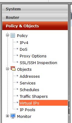
So, lets create a VIP. First lets navigate to Policy & Objects, Objects, and Virtual IPs. Lets create a new object.

location

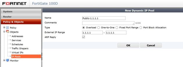
Now, lets input the information needed to have external connections reach our internal network. In this example my outside web server listening address is 2.2.2.1 (my fake public IP) , my internal web server at 172.16.1.10 and my answering interface (the interface accepting connections) is WAN1 (QXnet). So, start out naming the VIP something that will have meaning to you. Then select the incoming interface, and apply the correct IP information. You will then have the option to do a port forward (1 port or a range forwarded into the server), or a 1-1 nat, where all ports are forwarded. If you do a Port Forward, select the protocol, and then set the ports.

Vip-Creation

In this example I am allowing port 80 on my public IP to be forwarded to port 80 on my private server.

Great, we have created the VIP object. But, as of now no traffic will be allowed to go to the private server. We have to add a Firewall policy to allow that traffic to the VIP.

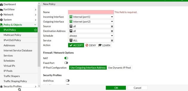
Lets navigate to Policy & Objects, Policy, IPV4 then create a new policy.

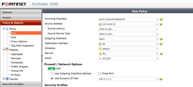
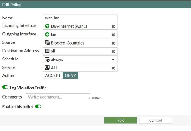
Below shows the settings. The settings read like this : Incoming Interface – This would be where traffic is coming from, in this case the WAN1 interface. Source address: this would be the actual address its coming from, in this case it could be anyone on the internet, so I will select all. Source users, and devices can be left blank. Outgoing interface: this is were the traffic is going, in this case its going to my server located on my LAN interface. Destination address, this is the tricky part. The destination address will be the VIP you created. In 5.2 notice the ICON. Its different then normal address objects, thus specifying, if your name didn’t, that this is a VIP.  You then have to specify the server you want to allow in, I am creating the VIP to allow HTTP into the network, so I will only specify HTTP traffic to be allowed in.

For traffic coming into the firewall we do not need to NAT this traffic, please turn this off. In 5.2> it is on by default when you create a policy.

If you require any UTM features to be on, this is the time.

Policy

That’s It! Fortinet makes it very easy to create these VIPs.

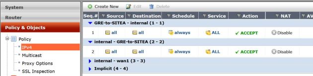
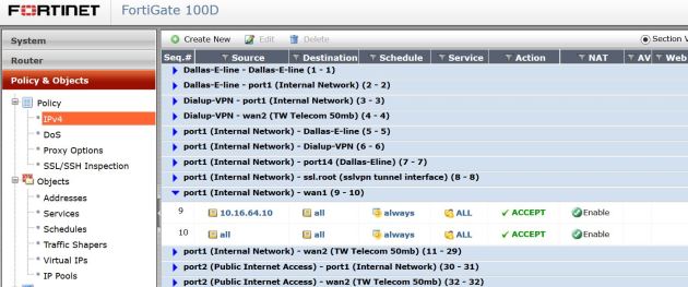
If you are not sure if your VIP is working, there are many ways to check/troubleshoot. One way would be to test it, does your server answer? You can also do an online port scan using any many tools online. you can also check the hit counts on the policy (See below). The hit counter should be there by default, but if not add it in by right clicking on the tool bar and selecting Count as one of your columns. I have used the hit counter many times to troubleshoot my VIPs not working. For example, if I try to access my server VIA the public IP, and I get hit on my policy – I know that everything is correct on my VIP. I will then make sure my ports/server settings are correct. You could also do more advanced troubleshooting like debugging the traffic, or do a packet capture on the firewall.

hit-count

Creating a Fortianalyzer to Fortigate IPSEC Secure connection

The Fortianalyzer is a great product. It can give very deep analysis of exactly what is going through the network and allow you to create/schedule reports to show this data. You also have very quick detailed monitoring at hand with the Fortiview. By default the Fortigates connect to the FAZ  via SSL, all logs are encrypted. Recently, and I am not sure what the issue is, I have been having issues with certain FGTs connecting to the FAZ via SSL (I think its a cert issue..but still checking). So, we have a different option, to use IPSEC to create a tunnel and allow everything to be encrypted that way. This works great.

What we need to do

FAZ: add the device manually in the FAZ, enable “Security”, change the Local ID, Set the PSK.

FGT: Go in through CLI, disable SSL encryption, enable IPSEC, set the PSK.

So lets go to step one – adding the the device in the FAZ.

Log into the device, and select whatever Adom you want to add the FGT into. Then select to add a device, once this pops up fill in the needed info, you will need an admin account.

device-add

Select “Next” and fill in the needed info, you will need the S/N for this.

device-add2

Once that is added you will be able to edit the device. Right click on the device name and select Edit.

From here you will need to enable IPSEC by checking “Secure Connection” and change the PSK. Notice Local ID this is what will identify the FGT. By default its the S/N but you can change it to anything. In this case I am using FGT1.

Device-add-3

Now you should see something like this, notice that “Secure connection” is red.

Device-status

Great, now its time for the device settings. I am going to do this through the CLI, its the only way to set the PSK as far as I know.

The commands are listed below. One thing to note is that once you select “Encrypt” you disable SSL and enable IPSEC.

fgt-1

After all the commands are entered, you should be able to go to Log-Log Config-and test the connection to the FAZ. It should pop up that everything is working as listed below:

testing-1

Lets check on the FAZ, to make sure everything looks correct.

faz-status

Ok, this all looks great. That’s it, now we are using IPSEC to encrypt the logs. Its a good alternative to SSL if you find your self in the situation that the FGTs will not connect do to cert issues.