Fortigate Login Banner

Login banners are a great way of explicitly asking users if they are authorized to log in, show your legal terms, or just leave a message for users when they log in such as ‘don’t forget to backup the configuration’ .. etc.

In Fortigate login banners are very easy to write and enable. Just a few options need to be tweaked.

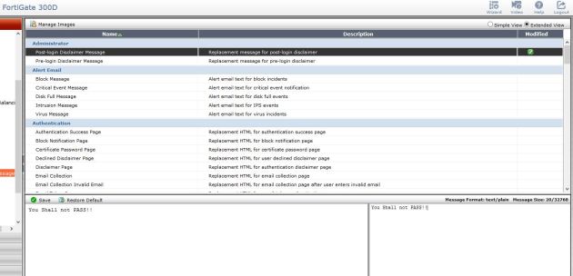
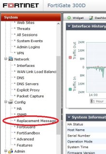
The banner can be modified by going to – system – config – replacement messages. Select the extended view at the top right, and then you will see the login banner, both pre and post. Pre is show before you login, post is shown after. The messages can differ. After you modify the message, remember to save.

replace

Switch to extended:

extended-view

Editing banner:

shall-not-pass


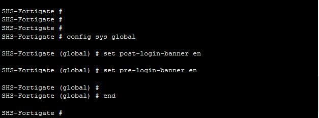
Now we need to enable the banner to show in CLI – to do this modify the global settings .

cli

Now the banner will prompt.

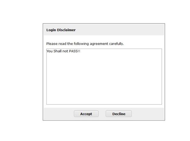
If Pre-login-banner is enabled the banner will show as soon as you go to the page to login – before you even get prompted to log in. Post will prompt after login. This is what the banner looks like:

banner-show

Fortigate FSSO and LDAP source IP

I was presented with a scenario the other day where we had two sites connected with a Site-to-Site VPN. The VPN was up and working great, but FSSO and LDAP would not connect to servers on the other side of the VPN for lookups.

This made sense because I knew the fortigate was using its outside (Public) IP for lookups and obviously that was not in my Phase 2 subnets to encrypt. So how can I change this?

Note, these steps change the source IP that the FGT uses to query LDAP or FSSO.

There are options in both objects (FSSO, and LDAP) In CLI to change the source IP address. See below

LDAP Source IP change

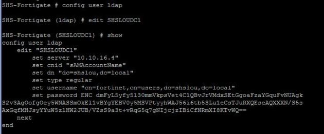
First log in through CLI, and edit the object, Then set the source IP. Once you end the CLI session it should be changed.

show ldap

Now set the source IP address of the connection

Set Source IP

Once you enter this and then end the session via the key word ‘end’ you will set the command.

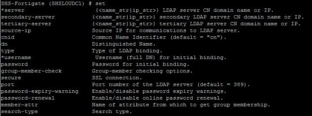
Before moving on to the FSSO settings, here is a list of options available:
options


FSSO Source IP change

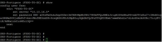
In CLI edit the FSSO object with the below commands, modify the source IP as below, and end the console to set the commands.

FSSO-show


fsso-source-ip

Once you enter this and then end the session via the key word ‘end’ you will set the command

That should be it! You modified your source IP to something in the encryption domain and it should now talk to the remote side and be able to do lookups.

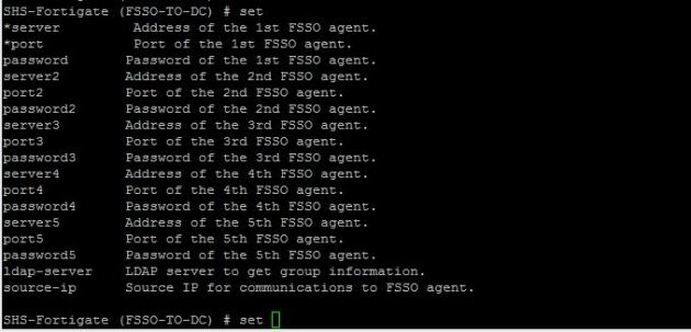
Just in case below are all the options available under the FSSO.

fsso-show-options

Enabling SSH on Dell Powerconnect 5000/6000/7000

No one is probably trying to even do this anymore due to the new Dell switching lines, but thought I would see if I could help. I had this issue the other day, and it took a good bit of googlefu before I could find my answer .

The problem I had was getting SSH enabled on a Dell PowerConnect 7048P. I created my user/passwords , and then generated my certificate, and then enabled the SSH server.. I got this error

PC-7048(config)#crypto key generate rsa

RSA key generation started, this may take a few minutes……..
RSA key generation complete.

PC-7048(config)#

PC-7048(config)#ip ssh server

SSH could not be enabled.

Hmmm… Why is that, all of my needed components are there, so why is it not working. The reason is there is no Cert to be used by SSH. These models use the Digital signature Algorithm (DSA) Certificate instead of the RSA cert. SO we need to create the DSA Cert.

PC-7048(config)#crypto key generate dsa

DSA key generation started, this may take a few minutes………………….
DSA key generation complete.

PC-7048(config)#ip ssh ser

No error!! and it works just fine.

Good reading for the comparison of RSA vs DSA: http://security.stackexchange.com/questions/5096/rsa-vs-dsa-for-ssh-authentication-keys

Cisco Errdisable and recovery options

Errdisable is an extremely cool feature on Cisco switches that can place a port into a disabled state due to some reason/errors on the port. There are many reasons a port can be disabled:
Duplex mismatch
Port channel misconfiguration
BPDU guard violation
UniDirectional Link Detection (UDLD) condition
Link-flap detection
Security violation
Port Aggregation Protocol (PAgP) flap
DHCP snooping rate-limit
Incorrect GBIC / Small Form-Factor Pluggable (SFP) module or cable

And many more. Here is Cisco’s Documentation :http://www.cisco.com/c/en/us/support/docs/lan-switching/spanning-tree-protocol/69980-errdisable-recovery.html

The beauty of this feature is that if I screw something up, or if for example a I configure Port security and there’s and error it will shut down the port so that horrible things like loops or security violations are not allowed. By default Err-disable will shut down the port and it will take a manual shut/no shut of the port.

Finding out what ports and why they were put into ERRDisable

It is very frustrating to see ports come online, and then get shut off for some unknown reason. We can find out why they were shut off with a few simple commands

to find out what ports might be having errdisable problems we can do a :

show interfaces status errdisable

This command will show us all ports that are currently shutdown due to errdisable and the reason why. You can also get more specific with the :

err-reason

show interfaces gig 1/0/12 status errdisable

to get more information just from that port.

You can of course also see what is happening through the logs or syslog showing something like this

%SPANTREE-SP-2-BLOCK_BPDUGUARD: 
   Received BPDU on port GigabitEthernet4/1 with BPDU Guard enabled. Disabling port.

Auto Recovery options

So how can we make this a temporary setting – what if I was putting a switch in a school, and I want to make sure that if someone plugs up another switch, and I see a BPDU, I shutdown the port and then want that port to come back online in x amount of time. There are two parts to that problem. 1, you have to set BPDU Guard on the port or whole switch. Once that is setup, it will automatically be put into Err-disable state. Now, to bring it out of that state automatically, we have to modify the err-disable recovery option, and the cause option (unless we want all causes to automatically come back up – which might not be good). There are a few commands to help us figure out what has been set already:

Show errdisable recovery

This command will report back to you any recovery options that have been set, and the default recovery value of 300 seconds.

recovery

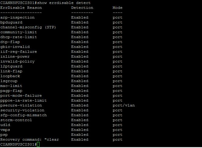
Show errdisable detect

This command will show you if we are detecting this error. By default all should be detecting.

err-detect

So, lets say I only want BPDUguard to recovery iteself every 60 seconds. This is what I would do:

Config t

errdisable recovery cause bpduguard

errdisable recovery interval 60

This will effectively enable recovery only for BPDUguard, and will change ALL recovery times to 60 seconds.

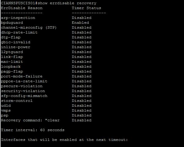
The following is the show recovery after the change:

err-after-change

Errdisable is a great feature that Cisco implements in almost all of their switches. It can really save some pain if you incorrectly configure a etherchannel, or have a bad cable that is really sending a ton of CRCs.

Fortigate Radius SSO with Ruckus 802.1x logins using NPS

This is an amazing method for getting users in their correct groups in Fortigates. This way we can apply different security profiles to individual groups, all through one 802.1x login. This example is using Ruckus wireless , but will work exactly the same for any wifi vendor..

This method works by using 802.1x WPA2/AES logins on the Ruckus , and passing the users info over to the Fortigate by Radius accounting. Then on the Fortigate we are using RSSO (Radius single sign on) groups to collect the username/group that is sent to the Ruckus by the Windows NPS server. Lots of moving parts here, but it is really simple. I have had problems finding good documentation about Fortigate’s RSSO profiles – but they work great.

The goal of this project/entry is to have the Fortigate know the Username, IP and group (if assigned) of the user who just authenticated to the wireless network. Once you know these things you can apply different UTM policies to users VIA RSSO groups in the Fortigate. There are many good scenarios and uses for this – one example that I have is for a school network. I set this up recently for a school that has students and faculty authenticate through the same Ruckus controller, but to different 802.1x WLANs (SSIDs: Student and Faculty). The fortigate can then apply correct policies to each user (student or faculty) and therefore lock down student web surfing much more than a faculty member. You might be saying – you could just use captive portal on the fortigate,with LDAP groups. I would say yes, but that is another step users have to take, and its called “Single Sign on” for a reason.

So what is needed to make all this happen: Ruckus wireless using 802.1x, NPS (or any radius server) , Fortigate  – that’s it.

I am going to assume that we already have Ruckus using 802.1x and NPS with no problems.

I had trouble at first setting this up, because I thought that that the NPS server should send the radius accounting info to the Fortigate, I was wrong. The controller is the Authenticator – therefore the device that knows about the authentication, and needs to pass on the info to the Fortigate. The Authenticator (Controller) needs to send the radius accounting info to the Fortigate.

That means you have a AAA server setup on the controller for 802.1x authentication, and a AAA radius accounting server pointing to the Fortigate.

Setup Radius accounting between Ruckus and Fortigate

First we need to create the connection between Ruckus and Fortigate via radius accounting.

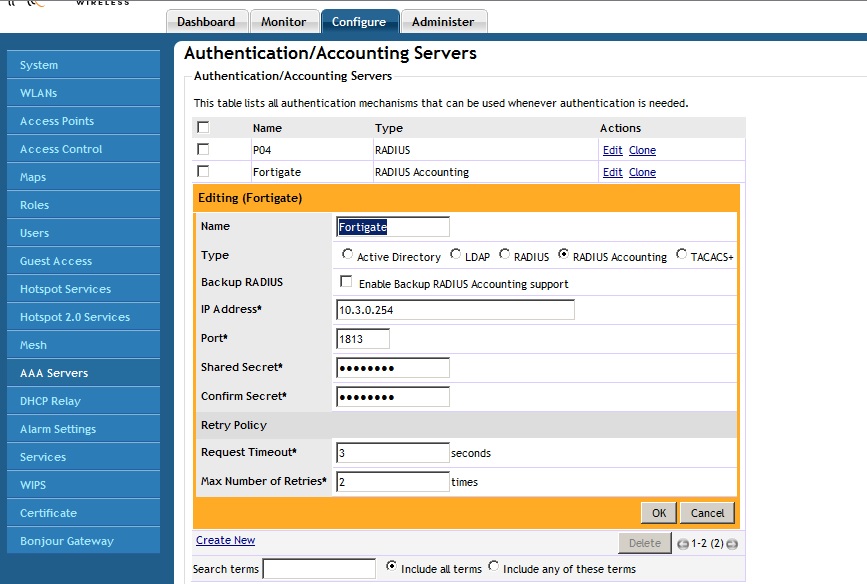
On the Ruckus system, go to Configure – AAA servers – create a new server. Then click the box that says “Radius accounting” Fill in the IP of your Fortigate, and create a PSK between the two.
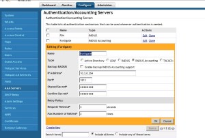
Ruckus-acct

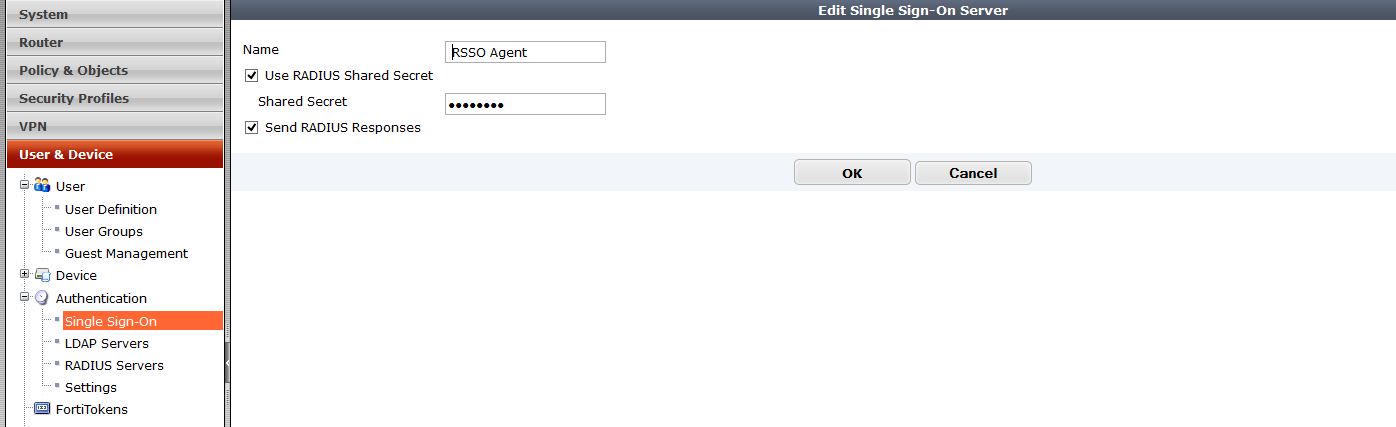
Next on our Fortigate we need to create a RSSO profile for the Ruckus system.
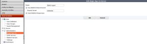
rsso-agent

Feel free to name this Ruckus or whatever. The PSK has to match what you created on the Ruckus system. By default the RSSO profile uses the Class variable to match the users. You can change what to match, for example you could match by NAS-Port, User-Name, Class, etc.

So, if we go into CLI we can modify many of these settings. Below are the settings I have used

config user radius
edit “Zonedirector”
set rsso enable
set rsso-secret ENC eoTXOqectoW0sjb5lLVW/7rr3BB0DocxlKeW64yfoIq7NTblyMc1TT9/V2M8m2LJmotwNrDYS+hOBSWV68wWULjuT88tOZHli7Nqqe8k5hoK4iHmLuG6x9R7apR9b+JU6O48mY8jiUaf48pY8wamagNdOALtrew6k+yWFzfd7gzo+qgag2sOI+Q46GnI1ybGPo6YQQ==
set rsso-endpoint-attribute User-Name
next
end

Next we need to modify NPS to send the values that we will match on the Fortigate. In this example I am matching I am saying that if any Domain users authenticate through the ZD, then send the IP/Username/”Tag” to the Fortigate so it knows who to apply the correct firewall policy to. My “Tag” I am sending in is the Class Variable of “Domain Users”..  Something to note is this is not the given AD group, but a variable I am assigning that just references the group. I could say “Social media” if I wanted, then match on that.

So lets modify the Microsoft NPS policies to reflect what we need.

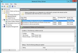
Remember, we are going from the assumption that 802.1x is up and working, and NPS is great. So, how do we match a variable from NPS on the fortigate? We could really use a ton of different variables. Lets use the class variable. To assign the class variable we will modify the the Network Policy in NPS that we want to apply a to a certain criteria.
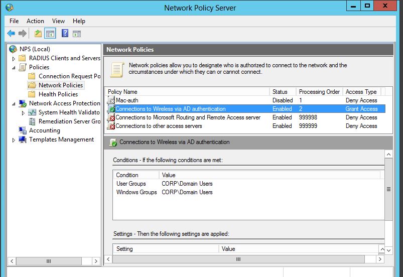
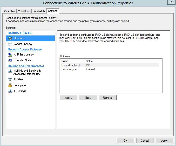
nps-policy1

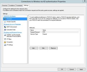
I will modify my “Connections to Wireless VIA AD Authentication” Policy. Then once, you edit the policy and go to “Settings” tab, there will be a few attributes already listed . You may have some already or not. We will add the “Class” variable, and then assign it to what ever value we want to match in the firewall group. In this case I am setting my value to “Domain Users”.
class1

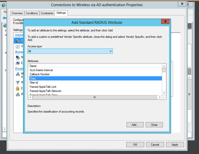
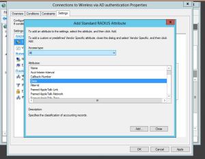
So from the settings tab, lets click “Add” under the Radius Attributes standard section.
class-2

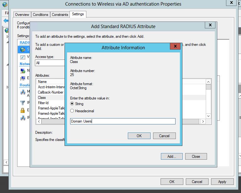
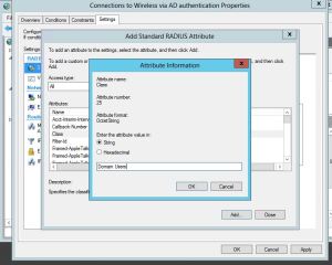
Select “Class” from the list of attributes that comes up, it will then  ask you to enter a string that you want to set. This is the Keyword you will use to match the user to group in the Firewall. Just like use a FSSO group and matching the domain group. Some examples might be students vs teachers, or Domain users.
class-3

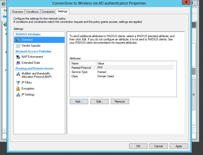
Press OK, and now we have the variable added, you can confirm as seen below:
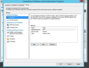
class-4

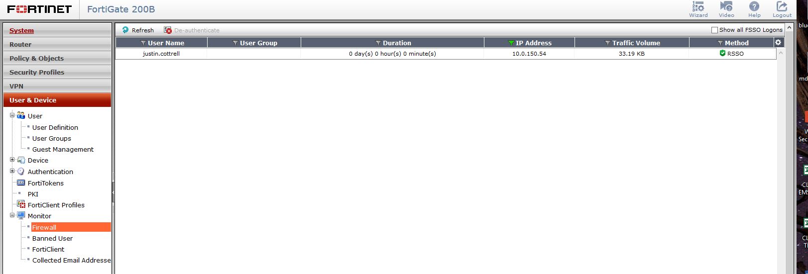
Great, now we have the hard part done. Now, have some users log in to wireless, and see if you get correct RSSO users found in the firewall. you can check this my navigating in the firewall to User&Device – Monitor – Firewall
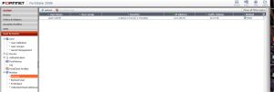
No-group

Awesome, it found my username, and my IP, but my group is blank, how can you apply a policy to user if they have no group? The answer – is just the same as the FSSO. If you do not have a firewall policy that references the Radius group that you created then no group, no filtering, nothing. So you need to create a new firewall policy and select the RSSO group you created as the source group. In my example the group is called Radius Domain Users.
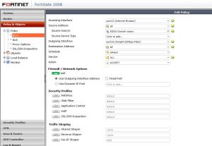
firewall-rss-policy-creation

To show a policy example check out below: My domain FSSO is above my RSSO policy.

firewall-rss-policy

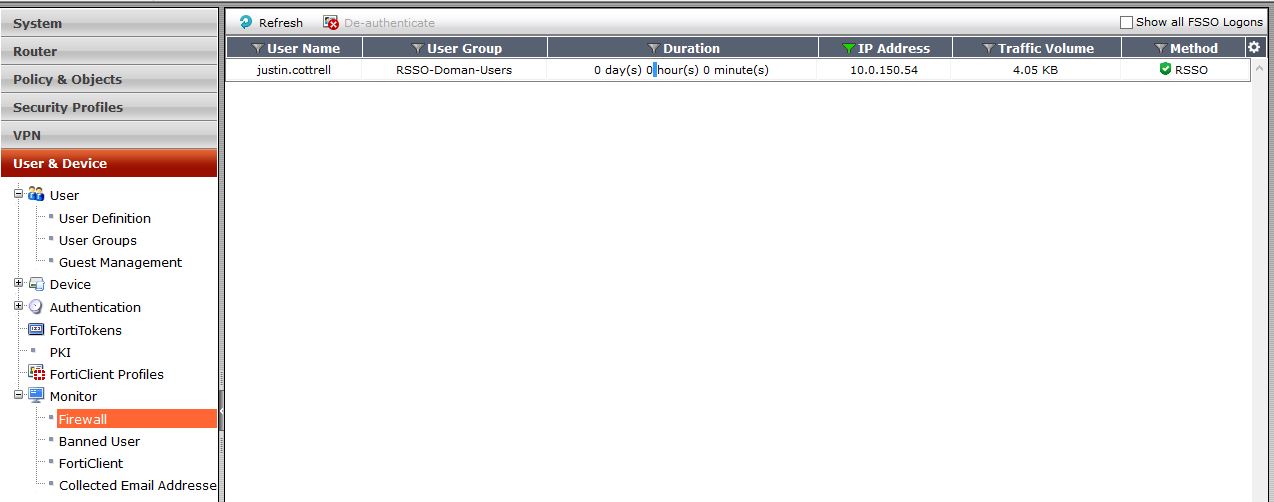
Now that that is created and enabled, lets check the user monitoring – BAM! there it is, my group included.
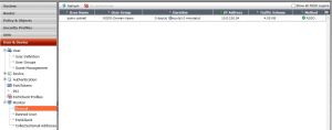
Radius-user

Using RSSO and 802.1x is awesome, it allows you to kinda use a single pane of glass aspect and have Firewall, and Wireless be able to know who the user is just my them logging into the wireless network. Also, using 802.1x for wireless authentication and Key management is very secure. Having users known that are on wireless no matter what device can really be beneficial in reporting, either through Forticloud of FAZ.

Cisco Router IOS Policy-based NAT for VPN traffic

I thought I would blog on this. It could be useful for someone who might have an IOS router instead of an ASA and need to create a IPSEC Site-to-Site VPN to a remote peer, then NAT VPN traffic to a different address or subnet if needed, or the local subnets conflict with each other.
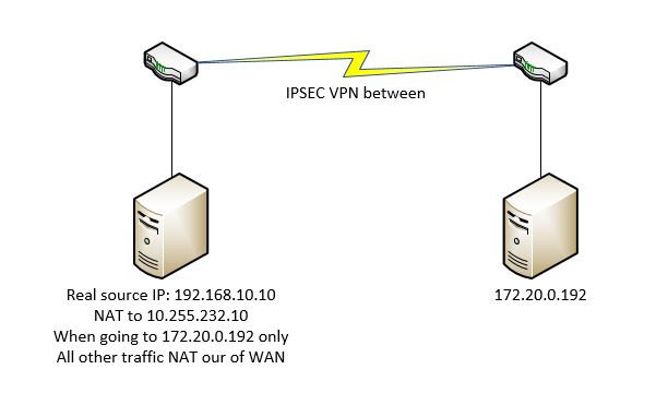
Here is a nice little Visio to kind of show what I am going for with the traffic:

vis

Because of duplicate subnets on both sides, I need to nat traffic going to 172.90.0.20 from 192.168.10.10, otherwise traffic should flow normally. How can I achieve conditional nat? By using a route-map and then natting only the traffic in the Route-map. So, lets get our VPN setup first. Remember, we add the NAT network or host IP to our interesting traffic ACL that will be used to define our Phase2

These are my commands:

ip access-list extended VPN-to-Remote
 permit ip host 10.255.232.10 host 172.20.0.192

crypto isakmp policy 50
 encr 3des
 authentication pre-share
 group 2
 lifetime 28800

crypto isakmp key … address 1.1.1.1 no-xauth

crypto ipsec transform-set Transform esp-3des esp-sha-hmac

crypto map Crypto 6 ipsec-isakmp
 set peer 1.1.1.1
 set transform-set Transform
 match address VPN-to-Remote

That pretty much gets the VPN up and going. Now for the interesting part – we need to create a new ACL, match my private 192.168.10.10 address and the destination address of the remote server, then match that ACL in my Route-map.

ip access-list extended Nat-for-VPN
 permit ip host 192.168.10.10 host 172.20.0.192

route-map VPN-to-REMOTE permit 10
 match ip address Nat-for-VPN
!

Great! So, we now have the route-map created.. so now what? We need to create a NAT statement that references my Route-Map. Then of course with any VPN we need to modify the “NO-NAT” ACL to include the traffic for both the 192.168.10.10, and the 10.255.232.10 to my remote destination.

ip nat inside source static 192.168.10.10 10.255.232.10 route-map VPN-to-HCN extendable

ip access-list extended NO-NAT
 deny   ip host 10.255.232.10 host 172.20.0.192
 deny   ip host 192.168.10.10 host 172.20.0.192

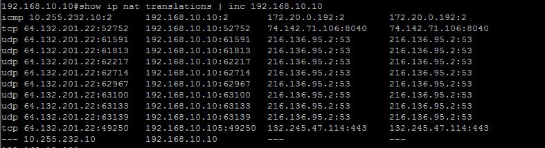
Now, if we try to access the remote side, does it work? Yes it does, but lets check to see if our nat is really working. It is! As you can see, 192.168.10.10 going to 172.20.0.192 is being natted into 10.255.232.10, but all other traffic gets natted out of the WAN interface.

nat1

Lets just check for translations of 10.255.232.10

2

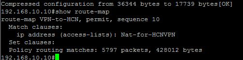
Bingo, everything works great. Lets make sure that we are getting hits on our Route-Map.

route-map

Cisco Duplicate IP address 0.0.0.0 ERROR – IP Device Tracking/NMSP

Recently I was seeing this error pop up on many Windows desktop clients:

The system detected an address conflict for IP address 0.0.0.0 with the system having network hardware address Ed-Ef-A9-B8-CC-2E. Network operations on this system may be disrupted as a result. Mac will vary.

After some research I found http://www.cisco.com/c/en/us/support/docs/ios-nx-os-software/8021x/116529-problemsolution-product-00.html

To give some highlights : “Cisco IOS® uses the Address Resolution Protocol (ARP) Probe sourced from an address of 0.0.0.0 in order to maintain the IP device-tracking cache when IP device tracking and a feature that uses it is enabled (such as 802.1x) on a Cisco IOS switch.

If the switch sends out an ARP Probe for the client while the Microsoft Windows PC is in its duplicate-address detection phase, Microsoft Windows detects the probe as a duplicate IP address and presents the user with a message that a duplicate IP address was found on the network for 0.0.0.0

So we now know the issue is with IP Device tracking, but what the heck does this do? IP Device tracking keeps an active list of devices that are connected VIA ARP. The function has as Cisco put it “Always been around”, is extremely beneficial when using MAC ACLs or using 802.1x. Recently it has really been used with Network Mobility Services Protocol (NMSP), this feature manages communication between the mobility service engine and the wireless controller in newer switches.

So how it works – When a  link is detected, it sends unicast Address Resolution Protocol (ARP) probe with a default interval of 30 seconds; these probes are sent to the MAC address of the host connected on the other side of the link, and use Layer 2 (L2) as the default source the MAC address of the physical interface out of which the ARP goes and a sender IP address of 0.0.0.0, — Bingo there’s are default IP that pops up.

So how do we remove device tracking? Easy huh.. just “no ip device-tracking” – this currently gives an error in certain firmwares. Firmware 03.02.02.SE and below give, the error is:

% IP device tracking is disabled at the interface level by removing the relevant configs

So, you could upgrade to 3.3 and then use the no ip device-tracking command, or if you cannot upgrade still disable all the features of IP device tracking. To do this:

Under each interface use commands:

nmsp attach suppress

no ip device-tracking max

I would recommend using a range command to get all the ports at once. This has fixed the issue for me.

Passing VLAN tags through a Ubiquiti NanoStation M5

I was working with some wireless bridge the other day that I had never used. I needed to get VLAN tags to pass through this wireless bridge, but for some reason they were not. I thought.. “this is a bridge it should pretty much be plug and play”. I was wrong. These bridges seem to do a great job, and are easy to setup, but I had problems finding out how to do this. I thought I would write up a simple post on how to allow VLAN tags to pass through this bridge.

My first issue was the bridges were on a very old firmware. I was on version 5.3, after finding some documentation I thought it was best that I upgrade. I upgraded all the way to the newest version which is 5.6.

Next I noticed that the WDS was not checked. To give some background on why this is so important:

WDS, which stands for Wireless Distribution System, is a feature that enables single-radio APs to be wirelessly inconnected instead of using a wired Ethernet connection.WDS connections are MAC address-based and employ a special data frame type that uses all four of the (MAC) address fields allowed in the 802.11 standard, instead of the three addresses used in normal AP <-> STA (client) traffic. (In the 802.11 frame header, address 1 is the destination address, address 2 is the source address, address 3 is the BSSID of the network and address 4 is used for WDS, to indicate the transmitter address.)

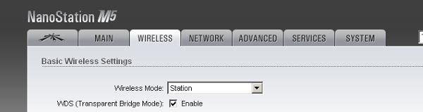
So that’s the reason that Vlan tags would not pass – WDS was not checked, so basically this was a acting as a switch instead of a transparent bridge.

Here are my settings that in the end fixed my vlan tagging issues. First had to upgrade the firmware, then next enable WDS on both aps, one being a Station (Client) the other being a AP. Last, of course make sure that switches both bridges plug into are trunk ports, and have the vlans created.

bridge2

bridge1

Configuring an IP address and enabling services such as SSH/HTTPS on Brocade Vyatta CLI

When Brocade purchased Vyatta I was nervous, but they have done a really good job with it. They keep it updated, and now have added a lot of functionality and increased services with the 6400 version. Both the 5600 (pretty much old vyatta) and the newer 6400 Vyatta IOS are for free from Brocade fro 60 days.

This blog entry is just showing some very simple things such as adding a IP address to an interface and enabling the HTTPS and SSH service. In another entry i will show how to use other user authentication methods for user logins. Although all of these commands are very easy, this post could help someone who might be in a bind.

Configure an IP address.

The Vrouter CLI has always been intuitive for me. Each config option is really an objects configuration. You can delete the config altogether or just an individual config setting of the object. To set the IP address first you have to go into configure mode.

configure

set int ethernet eth0 address 192.168.252.1/24

commitremember nothing is set, until this is entered.

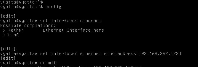
The image below shows these commands in the actual CLI.

ip-1

We can also save the config in config mode by issuing the command “save”.

That’s, it we have now set an IP address.So on to enabling SSH and HTTPS access.

HTTPS

To enable HTTPS we need to issue the command (from config mode)

set service https

commit

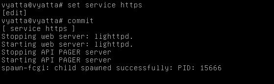
As you can see from the image below, after those commands are entered the Vyatta generates a certificate, and restarts its web server.

https2

SSH

Enabling SSH is as easy as the other commands.

From config mode

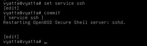
set service ssh enable

commit

You also have options to allow root login, set the listen address, and change the port.

SSH

Ruckus Self Service portal for Guest access

Ruckus brought in the Guest Self Service portal in firmware 9.10.0.0 build 218 – so if you are looking to configure it please install this update first (Check release notes for proper upgrade path). After we are on build 218, lets get configuring.

So the Ruckus Guest self service portal is Ruckus’s first step in creating an “on boarding”  process. It allows administrators to make sure that there is at least some kind of authentication on their guest WLANs. The portal gives guest users the ability to create their own guest pass, and the admin can set many options of the guest pass such as expiration, amount of devices that can be registered with this pass, and how the pass is given to the user – for example you can send it through text, email, just show it to them on the screen, or a combination of all. So this feature is great, and helps admins authenticate guest users with very minimal intervention.

So how do we configure this?

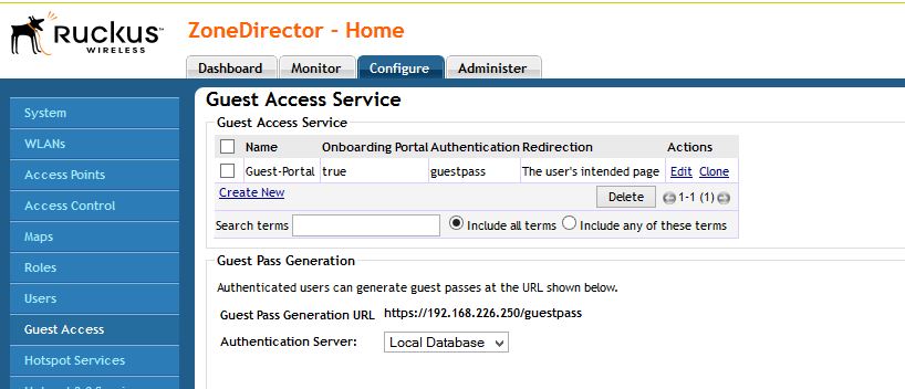
First we need to create a new Guest access policy. This is located under Configure – Guest Access. Create a new portal.

creation-guest

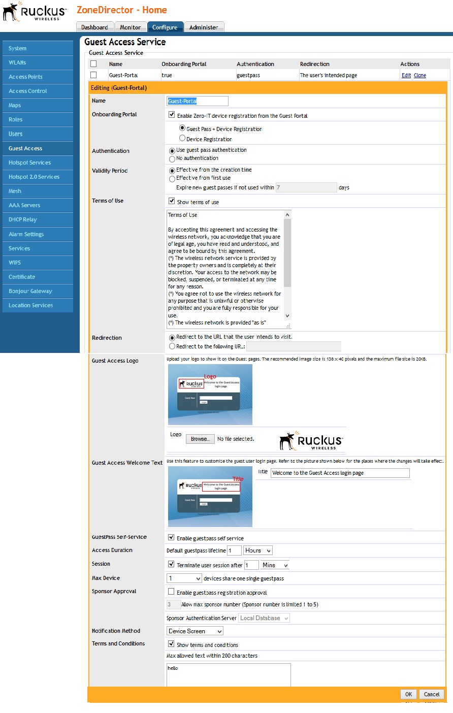
Lets now configure our portal page. A few options that are very important are:

Enable Zero IT Registration from the Guest Portal – Use this if you are also planning to register devices. I was confused by this at first. As you will see you have the option to use guest pass, or register a device. When you register a device you are just using Zero IT as normal to get on the secured network.

Authentication – Use guest pass for this. Since thats the goal.

Next you have a lot of options such as Terms of service and time out.

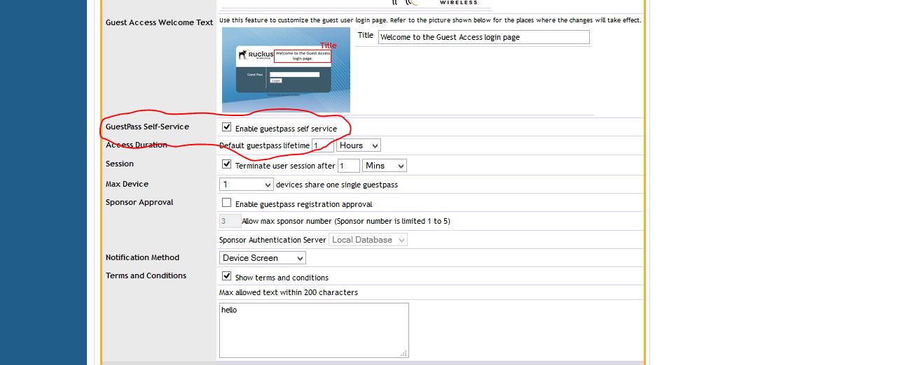
The main box you have to check is the “Guestpass Self-Service” box , you will then get a lot of options to do with that process and how to get the guest pass to the user. A few things to note, if you want to txt them, or send the pass through email you will need to configure a mail server and/or SMS server in the settings of the ZD.

checkbox

If you notice there is a small “Restricted Subnet access” – Its kind of hidden in my opinion. This is very important. If this is used for guest access more than likely you will want to make sure that guests cannot access internal hosts. This is where that is done. This or the Layer 3 access list. Remember Ruckus does the filtering on the AP, so having to have a ACL on the router is not needed. Below if the full Guest access config.

Settings

That is about it for the Guest portal. Now we need to create a WLAN and use it for our guest access.

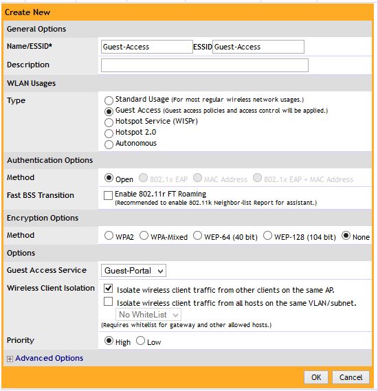
So, lets create a WLAN at configure – WLAN- create a new one.

SSID

Things to note – Select “Guest Access” Then select your Guest access Service portal you created.

Great!! All done, so what happens when you connect?

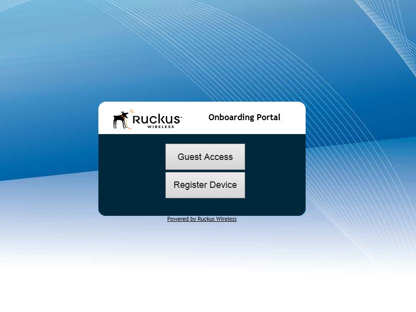
First you will be presented with the on boarding portal that asks if you would like to use Guest Access, or Register a device (Zero-IT).

register

Select “Guest Access”

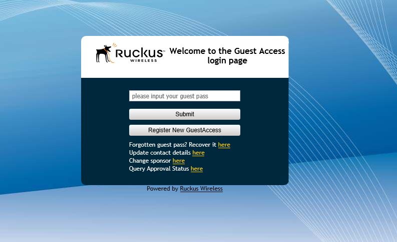
On the next screen it will ask you for your Guest pass, but you don’t have one yet. Select the button to create a new pass. Note that you have the option to Query the status. This is a feature if you want to approve guests of getting a Guest pass before they do.

guest-pass

On the next screen you will be asked to fill out your information.

pass-info

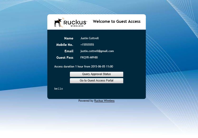
And here you go! you have your guest pass, which is valid for the length of time that you configured in the policy. Copy and keep this key. The ZD will automatically copy the key into the next page for you. Select to go to Guest Access portal.

guest-pass-show

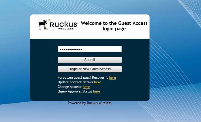
You can see the the ZD copied the key for you. Just Press submit.

last-guess

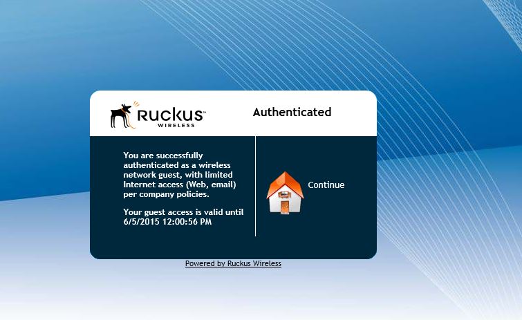
And there we go!! We are online. Ruckus does it again with making getting on Wifi easier. Now we have a built in On boarding portal.

authenticated

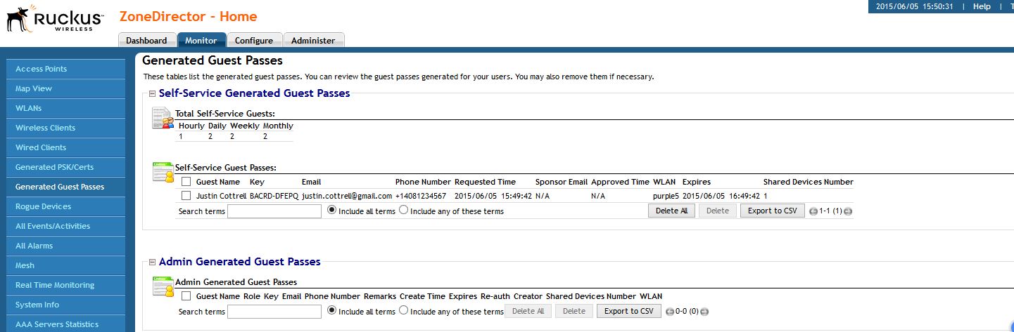
You can view the Guest Pass and its config under Monitor-Guest pass to find out who the GP was assigned to, when it expires, and you can delete them from here as well.

Generated

Ruckus has done a great job giving us a simple but effective way to on board users for Guest and/or internal use.