Creating a Fortigate Virtual IP – External to internal Port Forwarding

Hello, I noticed one thing I have never created a blog entry on creating a Virtual IP to allow access from the internet into a local server. This entry is for  a VIP and Policy creation on firmware 5.2> . Remember all the best documentation is located at docs.fortinet.com

So what is a VIP, a Virtual IP is one way to allow external traffic going to a Public address to be forwarded in to a Local server with a Private address. Basically, its a NAT object consisting of external IP and port and  Internal IP and port. Before this firewall will allow traffic to access the NAT object (VIP) it needs to have a Firewall policy allowing the destined traffic to the VIP.

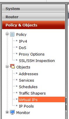
So, lets create a VIP. First lets navigate to Policy & Objects, Objects, and Virtual IPs. Lets create a new object.
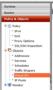
location

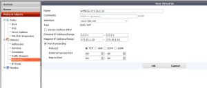
Now, lets input the information needed to have external connections reach our internal network. In this example my outside web server listening address is 2.2.2.1 (my fake public IP) , my internal web server at 172.16.1.10 and my answering interface (the interface accepting connections) is WAN1 (QXnet). So, start out naming the VIP something that will have meaning to you. Then select the incoming interface, and apply the correct IP information. You will then have the option to do a port forward (1 port or a range forwarded into the server), or a 1-1 nat, where all ports are forwarded. If you do a Port Forward, select the protocol, and then set the ports.
Vip-Creation

In this example I am allowing port 80 on my public IP to be forwarded to port 80 on my private server.

Great, we have created the VIP object. But, as of now no traffic will be allowed to go to the private server. We have to add a Firewall policy to allow that traffic to the VIP.

Lets navigate to Policy & Objects, Policy, IPV4 then create a new policy.

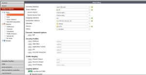
Below shows the settings. The settings read like this : Incoming Interface – This would be where traffic is coming from, in this case the WAN1 interface. Source address: this would be the actual address its coming from, in this case it could be anyone on the internet, so I will select all. Source users, and devices can be left blank. Outgoing interface: this is were the traffic is going, in this case its going to my server located on my LAN interface. Destination address, this is the tricky part. The destination address will be the VIP you created. In 5.2 notice the ICON. Its different then normal address objects, thus specifying, if your name didn’t, that this is a VIP.  You then have to specify the server you want to allow in, I am creating the VIP to allow HTTP into the network, so I will only specify HTTP traffic to be allowed in.

For traffic coming into the firewall we do not need to NAT this traffic, please turn this off. In 5.2> it is on by default when you create a policy.

If you require any UTM features to be on, this is the time.
Policy

That’s It! Fortinet makes it very easy to create these VIPs.

If you are not sure if your VIP is working, there are many ways to check/troubleshoot. One way would be to test it, does your server answer? You can also do an online port scan using any many tools online. you can also check the hit counts on the policy (See below). The hit counter should be there by default, but if not add it in by right clicking on the tool bar and selecting Count as one of your columns. I have used the hit counter many times to troubleshoot my VIPs not working. For example, if I try to access my server VIA the public IP, and I get hit on my policy – I know that everything is correct on my VIP. I will then make sure my ports/server settings are correct. You could also do more advanced troubleshooting like debugging the traffic, or do a packet capture on the firewall.

hit-count

Creating a Fortianalyzer to Fortigate IPSEC Secure connection

The Fortianalyzer is a great product. It can give very deep analysis of exactly what is going through the network and allow you to create/schedule reports to show this data. You also have very quick detailed monitoring at hand with the Fortiview. By default the Fortigates connect to the FAZ  via SSL, all logs are encrypted. Recently, and I am not sure what the issue is, I have been having issues with certain FGTs connecting to the FAZ via SSL (I think its a cert issue..but still checking). So, we have a different option, to use IPSEC to create a tunnel and allow everything to be encrypted that way. This works great.

What we need to do

FAZ: add the device manually in the FAZ, enable “Security”, change the Local ID, Set the PSK.

FGT: Go in through CLI, disable SSL encryption, enable IPSEC, set the PSK.

So lets go to step one – adding the the device in the FAZ.

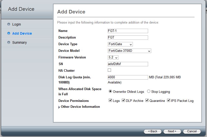
Log into the device, and select whatever Adom you want to add the FGT into. Then select to add a device, once this pops up fill in the needed info, you will need an admin account.

device-add

Select “Next” and fill in the needed info, you will need the S/N for this.

device-add2

Once that is added you will be able to edit the device. Right click on the device name and select Edit.

From here you will need to enable IPSEC by checking “Secure Connection” and change the PSK. Notice Local ID this is what will identify the FGT. By default its the S/N but you can change it to anything. In this case I am using FGT1.

Device-add-3

Now you should see something like this, notice that “Secure connection” is red.

Device-status

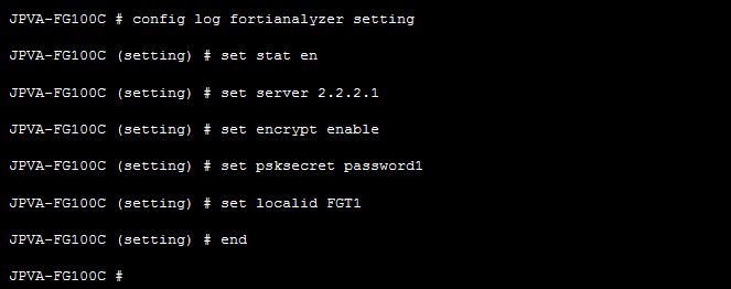
Great, now its time for the device settings. I am going to do this through the CLI, its the only way to set the PSK as far as I know.

The commands are listed below. One thing to note is that once you select “Encrypt” you disable SSL and enable IPSEC.

fgt-1

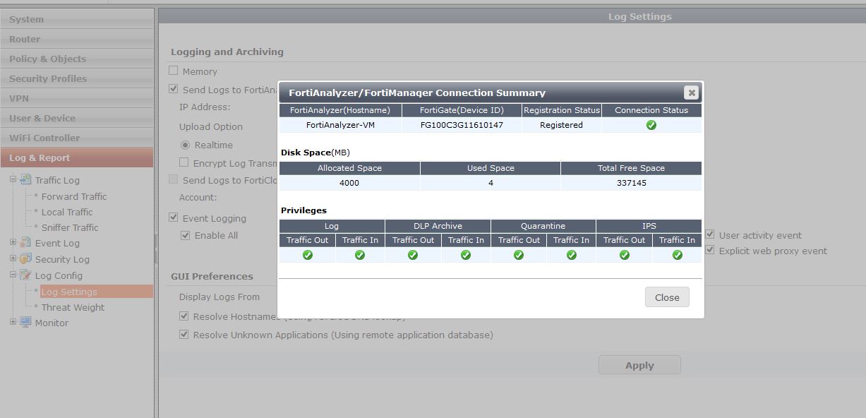
After all the commands are entered, you should be able to go to Log-Log Config-and test the connection to the FAZ. It should pop up that everything is working as listed below:

testing-1

Lets check on the FAZ, to make sure everything looks correct.

faz-status

Ok, this all looks great. That’s it, now we are using IPSEC to encrypt the logs. Its a good alternative to SSL if you find your self in the situation that the FGTs will not connect do to cert issues.

Cisco Router with AT&T DSL internet connection

I would say no one will find this useful, but I have DSL at home .. I know. The following config is how to add a Cisco router use AT&T DSL. I have done this many times but not in the last two years or so, I had trouble finding good documentation on google for exactly what I needed to do, so I thought I would share.

The main parts of the config needed are creating a dialer interface, setting the authentication and user/pass. Then associating that dialer interface with your Physical Ethernet interface, and lastly configuring the default route.

First lets configure the Dialer Interface

config t

interface Dialer1
ip address negotiated
ip mtu 1492
ip nat outside
encapsulation ppp
ip tcp adjust-mss 1460
dialer pool 1
dialer-group 1
ppp authentication chap pap callin optional
ppp chap hostname username@att.net
ppp chap password password
ppp pap sent-username username@att.net password password

Now lets associate that with a real interface:

interface FastEthernet0/1
no ip address
duplex auto
speed auto
pppoe enable group global
pppoe-client dial-pool-number 1
!

Next lets set our default route and point it out of the Dialer interface

ip route 0.0.0.0 0.0.0.0 Dialer1

Given we have all our user/pass correct in a minute you should be able to do a “Show IP int br” and see the ip address passed to us by our ATT DSL Modem in bridge mode on the dialer interface.

Cisco ASA 9.1+ Static Nat example

Below shows how to configure Static nat for a web server or some kind of application running on a internal host. Basically we are port forwarding port 80 from our public IP of 1.1.1.2 to port 80 of our internal IP at 10.1.1.2. In this example Auto Nat will be used. You could also use Manual nat, I have written another blog entry on this.  This is way different than 8.2 and below. Here we create an object and then modify the object with the Static port forward we want. I

In this example my ASA outside IP is 1.1.1.1, and I want the web server to answer on 1.1.1.2.

object network 1.1.1.2
host 1.1.1.2
exit

object network 10.1.1.2
host 10.1.1.2
nat (inside,outside) static 1.1.1.2 service tcp 80 80

Somethings to note- We could name the objects anything, I just chose to use the actual IP address. For example, you could do the command ” object network Webserver-Outside” and use that name to reference the outside IP address.

Next, if I want to allow access to 10.1.1.2 from the outside world, I will need an ACL.

access-list Outside-In permit tcp any 10.1.1.2 eq 80

access-group Outside-In in interface outside

Notice the internal IP specified in the ACL – that is there on purpose. Instead of referencing the External IP  you now reference the internal.

What if the outside address answering for my web server is the outside IP of the ASA?

No problem, just have to modify that one NAT entry. Instead of the public NAT object we use the “interface” keyword.

object network 1.1.1.2
host 1.1.1.2
exit

object network 10.1.1.2
host 10.1.1.2
nat (inside,outside) static interface service tcp 80 80

Cisco – Combing T1 interfaces to increase speed

Recently I was working on a project that had a very remote office that could not get high speed connections to its location. So, they wanted to combine 4 T1s that were already in the building to boost throughput. I had done this exact thing with many different ISPs but never Verizon/MCI . They do things just a bit different, so this entry is about what is needed to combine these links on Verizon’s network.

The key here is to use a Multilink Frame relay interface. This is a Virtual interface that will combine the individual interfaces. Its very similar to a BVI in concept. As Cisco says it: The Multilink Frame Relay feature enables you to create a virtual interface called a bundle or bundle interface. The bundle interface serves as the Frame Relay data link and performs the same functions as a physical interface. 

At the bottom of this entry all the parts of the config are listed

First we needed to create the MFR interface itself. The number is up to you, I created 34 – feel free to change that.

interface MFR34
mtu 4470 — MTU Verizon said to set
no ip address
no ip redirects
encapsulation frame-relay IETF – Encapsulation used.
frame-relay multilink bid u11111-11
frame-relay lmi-type ansi
!

Next we need to create the sub interface , which will be used as our DLCI and our L3 interface.
interface MFR34.500 point-to-point
description multilink:MLFR:3xT1
bandwidth 6000
ip address x.x.x.x x.x.x.x
ip nat outside
snmp trap link-status
no cdp enable
no arp frame-relay
frame-relay interface-dlci 500 IETF
!

Then we will bond the interface to our MFR interface.

interface Serial0/0/0:0
mtu 4470
bandwidth 1536
no ip address
 encapsulation frame-relay MFR34
load-interval 30
cdp enable
no arp frame-relay
!

The T1 and MFR config are below:

controller T1 0/0/0
cablelength long 0db
channel-group 0 timeslots 1-24
!
controller T1 0/0/1
cablelength long 0db
channel-group 0 timeslots 1-24
!
controller T1 0/0/2
cablelength long 0db
channel-group 0 timeslots 1-24
!
controller T1 0/0/3
cablelength long 0db
channel-group 0 timeslots 1-24
!

interface MFR34
mtu 4470
no ip address
no ip redirects
encapsulation frame-relay IETF
frame-relay multilink bid u11111-11
frame-relay lmi-type ansi
!
interface MFR34.500 point-to-point
description multilink:MLFR:3xT1
bandwidth 6000
ip address x.x.x.x x.x.x.x
ip nat outside
snmp trap link-status
no cdp enable
no arp frame-relay
frame-relay interface-dlci 500 IETF
!

interface Serial0/0/0:0
mtu 4470
bandwidth 1536
no ip address
no ip redirects
no ip proxy-arp
encapsulation frame-relay MFR34
load-interval 30
cdp enable
no arp frame-relay
!
interface Serial0/0/1:0
mtu 4470
bandwidth 1536
no ip address
no ip redirects
no ip proxy-arp
encapsulation frame-relay MFR34
load-interval 30
no arp frame-relay
!
interface Serial0/0/2:0
mtu 4470
bandwidth 1536
no ip address
no ip redirects
no ip proxy-arp
encapsulation frame-relay MFR34
load-interval 30
no arp frame-relay
!
interface Serial0/0/3:0
mtu 4470
bandwidth 1536
no ip address
no ip redirects
no ip proxy-arp
encapsulation frame-relay MFR34
load-interval 30
no arp frame-relay
!

Hot add Nic into Vyatta VM – no reboot required

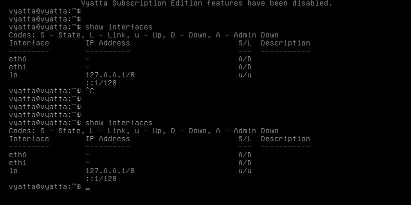
Recently I was asked about how to add a nic to a Vyatta VM, my reply “add it in VMware and reboot”- their response “We cannot reboot”. I asked why they can’t reboot and they said “If we were to reboot this Vyatta (Bring down the Client VPNs) then we would have to send out an email a ton of clients and let them know” – huge ordeal .

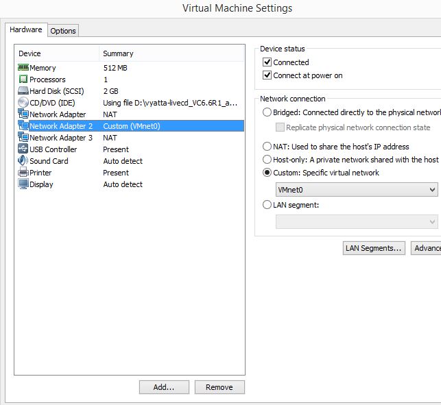
So we need to add a nic via VMware, and then have Vyatta recognize that nic right away, with out a reboot. So I added the Nic (see image below) in VMware:

Add-int

After I add the NIC, I can look on the Vyatta and see it still shows only two NICs.

showint

So, VMware added the nic but Vyatta(debian) never sees it. After trying to ifup/ifdown , service network restart – and many other commands it could never find it.

So, what is needed – we have to rescan the PCI bus to find the nic. Most Linux users are probably like — ya of course you do! But I just reboot and it works. In this case cant reboot.

To Rescan the PCI bus, we have to first change our permissions on that file, echo into that file, than change the permissions back. The commands to do so are:

configure

sudo chmod 0777 /sys/bus/pci/rescan

sudo echo 1 > /sys/bus/pci/rescan

sudo chmod 0220 /sys/bus/pci/rescan

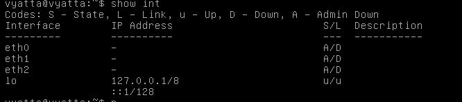
After doing that look at your interfaces:

int3

Now we see the interface and can configure it. This process should work with Debian no problem (since Vyatta is Debian).

Enabling LLDP in Ruckus wireless

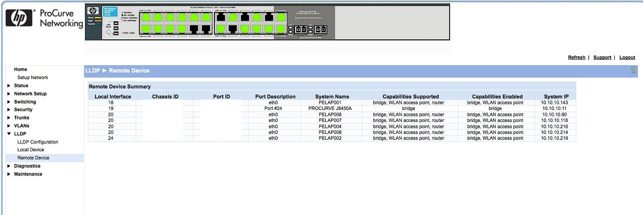
Ruckus has finally built in the ability to use LLDP to find Access points. I was so excited when I found this out, I installed the newest firmware and was ready to be blown away – and alas.. no LLDP. So, what was wrong? LLDP is not enabled by default! You have to go into the AP group via CLI and enable LLDP. No biggie.

This feature comes in software version ZDXXX 9.9.0.0.205 GA Software Release .

To enable LLDP – SSH into the zonedirector

Then after logging in run these commands

enable

config

ap-group “System Default”

LLDP enable

exit

exit

Here are some screenshots:

LLDP-3

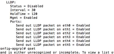
As you can see, by just doing a “Show” it is disabled:

LLDP-1

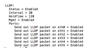
After running the command: “LLDP enable”

LLDP-2

And BAM: now I can find my APs no matter where they are plugged in at

LLDP-5-edit

Dynamic Vlans with Ruckus wireless and Microsoft NPS

Hello all, I recently was given a strange task. An office needs to have everyone in there office on different vlans. The reason for this is that each user is developing software and they need to test VIA wireless to other wireless  devices. Lots and Lots of broadcast, as well as different subnets. So, how can we separate each of these users wirelessly and give each of them their own “play space”? You can accomplish this a couple ways: We can have 100 different WLANs, each with their own Vlans, or use 1 SSID and use Dynamic Vlans to separate them out.

The tools I will be using are – Ruckus Wireless Zondirector, and APs, Microsoft NPS, and Wireshark to take a better look at what is happening at the packet level.

So first lets setup everything. We need to use 802.1x authentication for WLAN Access. I will not walk through all the steps here but definitely do another blog entry on setting that up. So lets assume as of now we have 802.1x working great for authentication.

Our next step is that we need to create new Security Groups in AD and add our users to them. I added groups that reflected the Vlan name. For example WIFI-VLan-150 and then added my user I want to get VLAN 150 to.

Next lets create our Radius Policies.

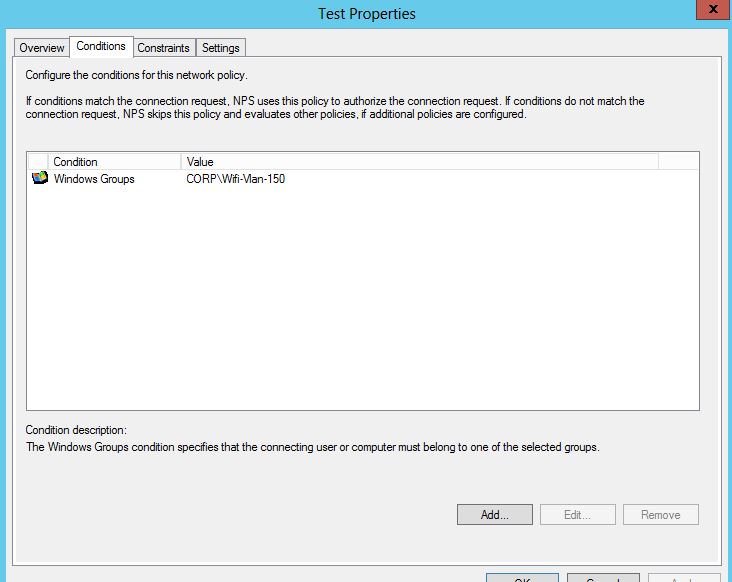
Create a new Network Policy- match the Group, add your Encryption and other settings. See below:

1

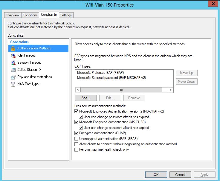
Then add your Constraints that you would like:

constraints

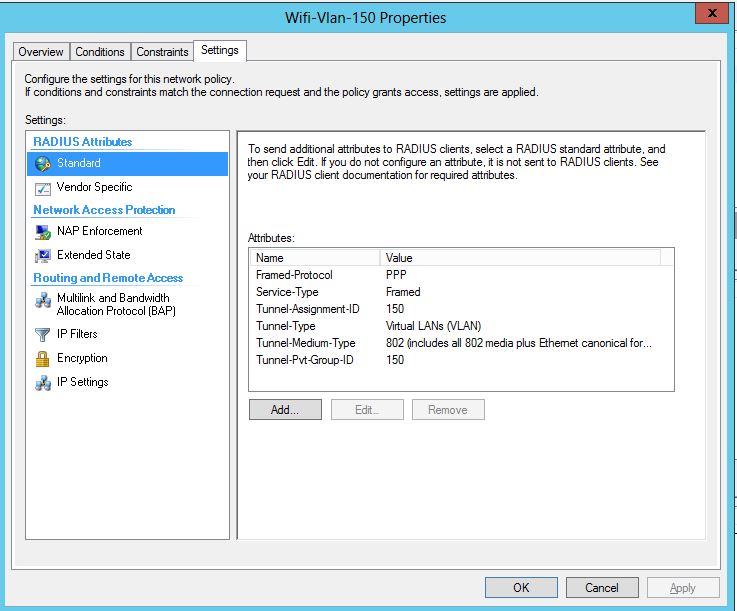
Next the magic happens – we have to add in our Radius attributes . These are Standard radius attributes. We will add 4 802.1x attributes.

Attributes to add:

1. Tunnel-Assignment-ID – String – Vlan ID.

2. Tunnel-Type – Select Virtual Lans (VLANS)

3. Tunnel-Medium-Type – Value – 802 – Commonly used for 802.1x

4. Tunnel-Pvt-Group-ID – Value – String – Vlan ID. Note – I did not add this at first, this attribute is what fixed my issue, and successfully pushed the Vlan ID to my client.

Here is a screenshot of all the attributes:

attributes

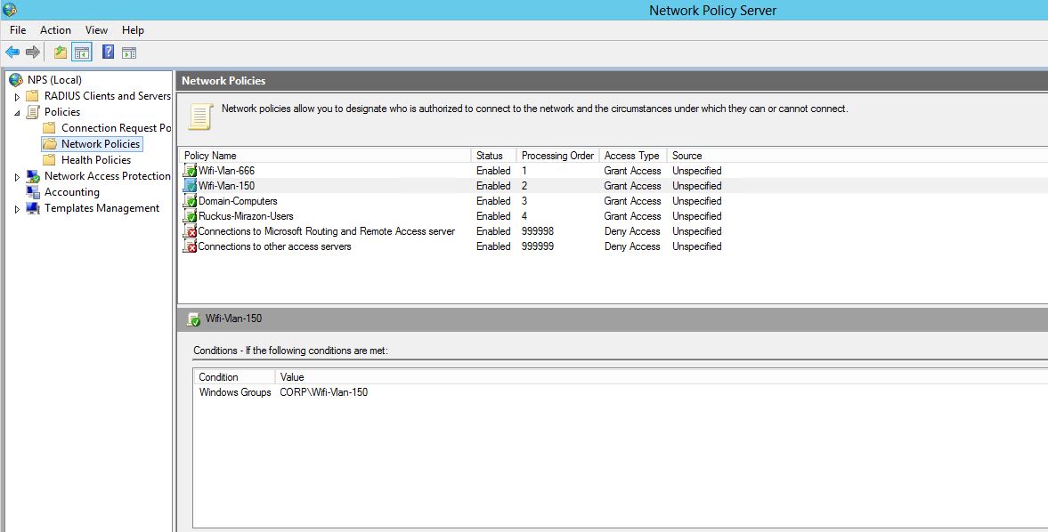
Make sure this policy is above your default policies. The next screen shot shows my order of policies. Notice I have one for 666 vlan, and 150. Then there is a domain computer, then a catch all for domain users.

policies

That’s it for Radius, now we need to create the WLAN for in Ruckus for our Dynamic Vlans. Remember, we are assuming everything works great with Radius authentication from the get go.

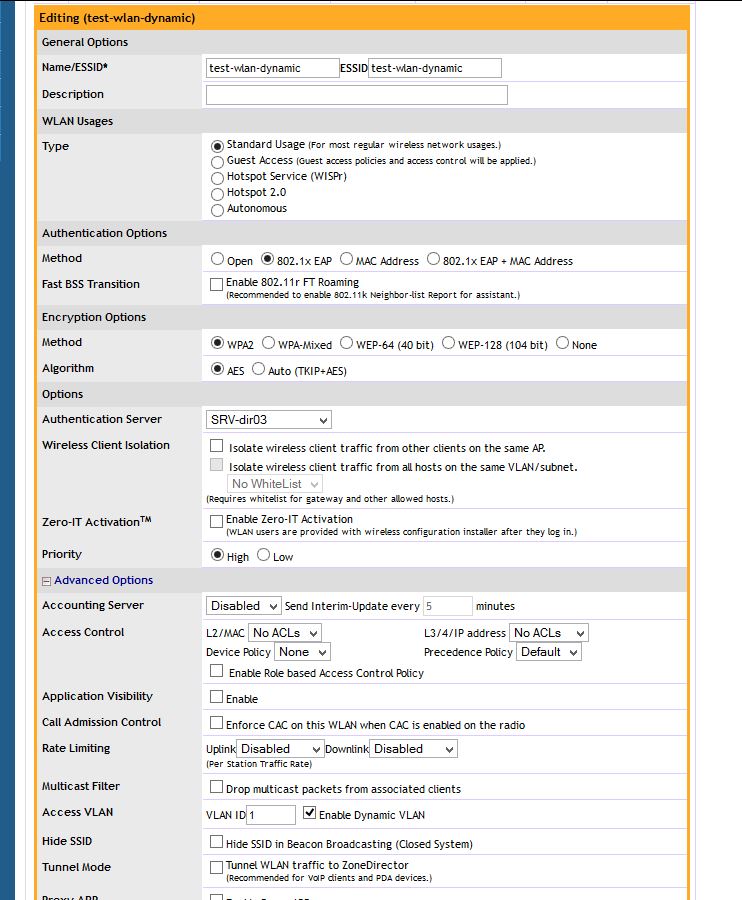
The main thing when creating the WLAN in Ruckus is to use 802.1x for authentication, and then under “Advanced” check the “Dynamic Vlan” box. You will notice I am using “SRV-dir03” For authentication (My Radius Server). Apply this and we should be golden.

ruckus

To check and make sure you are on the correct vlan/wlan you can always check your ip address or look into Ruckus and see what your info is. You Notice mine –

jc

Fortigate changing Switch/Interface mode

The entry is written for a 90d, but will work the same for a 60d or 80d, even some C models.

By default the Fortigate is in “Switch mode” you will only be able to see the “internal” switch, and cannot add or remove interfaces from this switch. In this mode you can add more switches, but not remove the current ports.

In the next few parts we will change the switch mode to interface, and be able to add/remove ports and switches.

Before doing anything to the Firewall make a backup. When we actually change the interface mode it will delete the IP address on the internal interface. So connect to a WAN or DMZ port and use the GUI, or make sure to be consoled into the firewall VIA the serial port (console).

First we need to remove any reference to the “internal” switch itself. If you have a default config then there will be only two. The internal->WAN policy, and the DHCP server under the “Internal” interface.

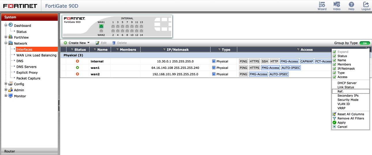
You can see all references attached to the interface by navigating to System-Network-Interfaces and modifying the settings to show the Reference tab.

int refJPG

once those references show up, you can click on the number and navigate to the exact location of that reference. For example, let say you added an address object a long time ago and added the interface. Bingo – shows you exactly where.

After removing all the references by deleting them (yes, deleting.. so make a backup!) you should now see a 0 balance in the references. We can now change the interface mode in CLI.

You can either do this through a terminal such as putty, or through the GUI CLI app. Remember after changing the interface mode, it will delete your IP address on the internal network. So do this VIA Console, or go to the GUI on the WAN or DMZ interface.

interface mode

Commands are:

config system global

set internal-switch-mode interface

end

Then click y to reboot the firewall, when it comes back it will be in interface mode.

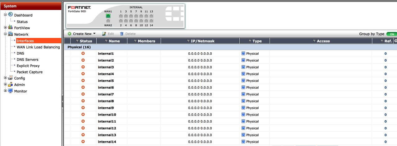
Once it is back up, login VIA the GUI on either the WAN1, WAN2, or DMZ ports. Then you should see something like this:

broke-interfaces

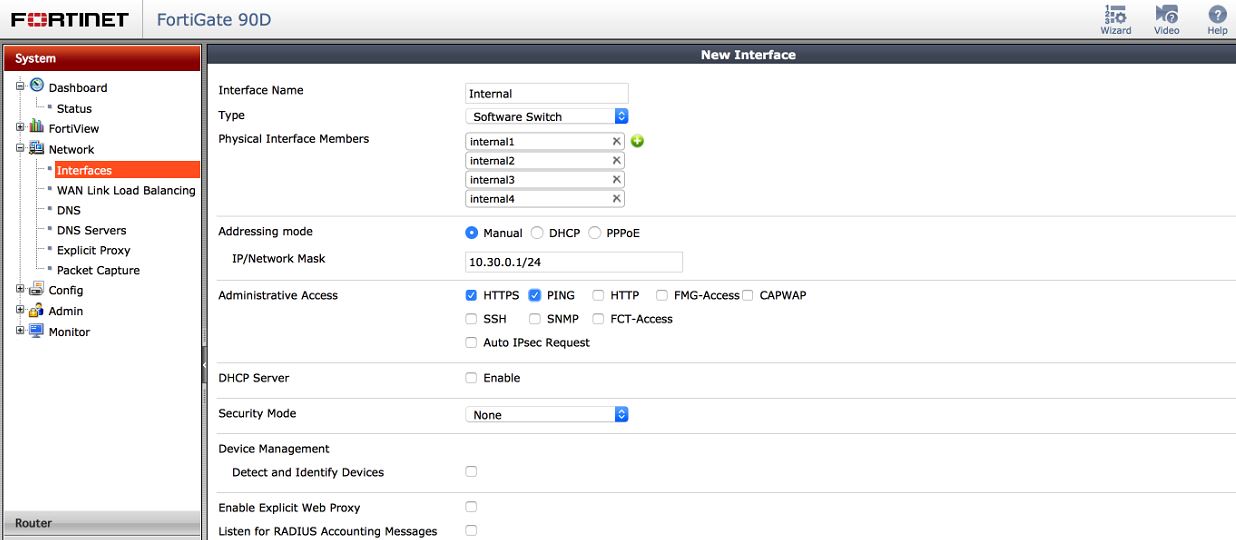
Now, under this page System-Network-Interfaces  lets click the “Create” Button. From here you can create your switch. Select the type as Software or hardware switch depending on your model. You can also add your ports, set the name of the interface and the IP.

internal-switch

Once you press OK, you should see your new interface listed under system-network-interface as seen below

show-switch

Recreate all of your policies, to allow access to and from and everything should work great. If you have any questions or I failed to explain anything please let me know.

Fortigate 5.2+ SSL VPN Address

You can use a different IP address to answer for the SSL VPN.

Lets say that your interface IP (The default IP address that is used with the SSL VPN) already has HTTPS (443) forwarded in to a internal server, and you really want the SSL VPN port to be 443. You have an option.

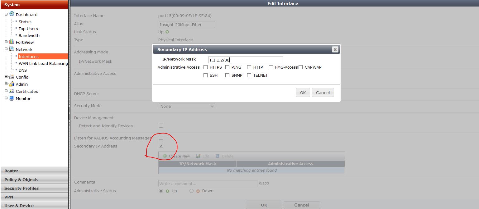
You can add a secondary IP  address under the WAN interface that does not have a reservation already for 443. Then use this IP address for the SSL VPN.

To do so:

secondary-ip

Add your secondary IP address – Note this has to be a public address, given to you by your ISP..

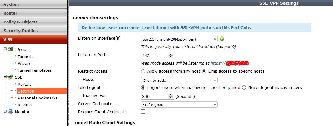
Then go into the VPN settings and modify the port for what you want. Notice that the address it says will work is still the primary IP, even though the secondary will work just fine.

ssl-settings-second